
Micro Automotive Plug In / PCB Power Relay
FEATURES
Micro size plug-in design
1 A, 1 B and 1 C contact forms available
30 Amps continuous carrying capacity
Contact switching capacity up to 90 Amps
Up to 125 degrees C operating temperature
PC Board version available
PC782
Max. Switching Voltage
Current Dependent, see curve page 2
1 Form A, 1 Form B or 1 Form C
CONTACT RATINGS
CHARACTERISTICS
Operate Time
9 ms. typical
Release Time
Insulation Resistance
7 ms. typical
100 megohms min, at 500VDC, 50%RH
Dielectric Strength
500 Vrms, 1 min. between coil and contacts
Shock Resistance
20 g, 11ms, functional; 200 g, destructive
Vibration Resistance
DA 1.27 mm, 10 - 40 Hz; 40-70 Hz: 5 g; DA 0.5mm, 70-100 Hz; 100-500 Hz: 10 g.
Power Consumption
1.6 W approx.
Ambient Temperature Range
-40 to 125 degrees C operating, -40 to 155 storage
Weight
Plug-In: 14 grams; PCB: 12 grams approx.
Sales: Call Toll Free (888)997-3933 Fax (818) 342-5296 email: pickerwest@sbcglobal.net URL: pickercomponents.com
3220 Commander Drive, Suite 102, Carrollton, Texas 75006
PC782 Rev B 4-13-04
PAGE 1
ORDERING INFORMATION
Example:
PC782
Model
-1C
Sockets available from Picker Components
Contact Form
Parallel Component
-P
CONTACT DATA
Material
Initial Contact Resistance
Service Life
Mechanical
Electrical
AgSnOInO (Silver Tin Oxide Indium Oxide)
100 milliohms max @ 0.1A, 6VDC
1 X 10
7
2 X 10
5
Operations
Operations
Normally Open
Nil: None; D: Diode; R: Resistor
Coil Voltage
-12
Contact Form
Max Switching Current
Break 30 Amps
Make 90 Amps
30 Amps
AgNiO 15 (Silver Nickel Oxide 15%)
Max. Continuous Current
Minimum Load
0.1 A @ 12 VDC
S
Drop Resistance
1 Meter height drop on concrete
1A, 1B or 1C
Normally Closed
Break 15 Amps
Make 20 Amps
20 Amps
Mounting Version
Nil: Plug-IN; P: PCB
-R
Internal Diode or Resistor available
Enclosure
C: Dust Cover, S: Sealed Case
PC782
PC782
Sales: Call Toll Free (888) 997-3933 Fax (818) 342-5296 email: pickerwest@sbcglobal.net URL: pickercomponents.com
3220 Commander Drive, Suite 102, Carrollton, Texas 75006
PAGE 2
COIL DATA
Coil Voltage
6
12
Resistance ohms
Nominal Operate
32
123
483
9.2
36.0
0.6
2.4
24
+ 10%
Allowable Voltage Max.
1 Form A & B
1 Form C
1 Form A, B & C
1 Form C
A, C, U, W
1.2
18.1
10.4
40.4
20.4
3.6
14.3
7.2
25
384
97
1 Form A & B
Voltage Max.
Nominal Release
Voltage Min.
(11.5)
.453
(8.0)
.315
(6.0)
.236
(4.5)
.177
(4.5)
.177
30
87
85 87a 86
(11.5)
.453
(8.0)
.315
(7.0)
.275
(4.5)
.177
(4.5)
.177
30
87
85 87a 86
(15.5)
.610
(26.0)
1.02
(23.0)
.906
(0.8)
.032 Typ.
(6.3)
.250
Terms. 30 & 87
(12.0)
.472
(4.8)
.189
Terms. 85, 86 & 87a
(5.7)
.224
(2.5)
.098
(2.2)
.087
Terms. 85, 86 & 87a
(2.5)
.098
Terms. 30 & 87
30
87a
87
85
86
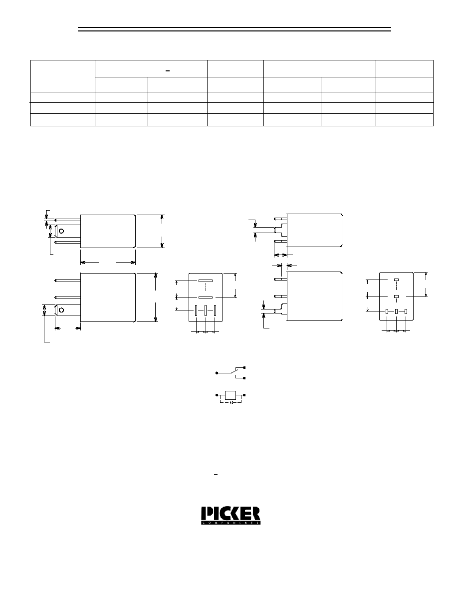
Wiring Diagram
Tolerances + .010 unless otherwise noted
Notes:
Contact Form C shown
On Contact Forms A & B Unused Pins are Omitted
Maximum make current refers to inrush of a lamp load
Make current of 120 Amps permissable with AgSnOInO contacts
In 85 degree C ambient reduce maximum coil voltage to 72%
Dimensions in Inches (millimeters)
Bottom View
PC Board Layout
Plug-In Type
PCB Type
(-)
(+)