
PRELIMINARY
PLL202-151
Programmable Clock Generator for VIA, ALI and SIS DDR SYSTEM
47745 Fremont Blvd., Fremont, California 94538 TEL (510) 492-0990 FAX (510) 492-0991 Rev 11/05/01 Page 1
48Mhz
24_48Mhz
PD#
XIN
XOUT
SDATA
SCLK
MULT_SEL1
XTAL
OSC
I2C
Logic
PLL1
SST
Control
Logic
REF
VDDCPU (3.3V)
CPUT (0:1)
APIC (0:1)
AGP (0:2)
PCI (1:8)
PCI_F
PLL2
� 2
Watch
Dog
WDRESET#
CPUC (0:1)
VDD
VDD_APIC (2.5V)
VDD
VDD_CPU_CS (2.5V)
CPUT (0:1)
CPUC (0:1)
PCI_STOP#
CPU_STOP#
FS(0:4)
VDD
FEATURES
�
Supports VIA P4M/KM266, ALI M1671 and SIS
645/650 Chipsets.
�
Programmable Spread Spectrum Modulation
from
�
0.1% to
�
1.5% with minimum step size of
�
0.012%. Selectable either center or down.
�
Selectable Spread Spectrum modulation profile.
�
AccuSkew
TM,
Programmable Precision skew
tuning channel with maximum
�
5% precision
over the variation of temperature, process and
voltage. Finest step starts with 80ps.
�
AccuDrive
TM
Programmable Output Buffer drive
strength with minimum 6mA per step. Selectable
double strength drive for REF1, AGP0, PCI5.
�
Programmable VCO frequency with one variable
�
Programmable VCO Output Divider.
�
On-chip 20 ohm series resistor for REF, PCI,
USB, ZCLK and AGP clock outputs.
�
6 differential DDR pairs or 12 SDR clocks.
�
8 PCI, 1 USB, 2 REF and 3 AGP clock outputs.
�
1 programmable 24MHz or 48MHz for SIO.
�
CPU frequency slow down to -30% if overheats.
�
Support 2-wire I2C serial bus interface.
�
Built-in programmable watchdog timer
�
Available in 300 mil 56 pin SSOP.
BLOCK DIAGRAM
PIN CONFIGURAT ION
Note:
^
:
Pull up (100k
),
v :
Pull down (100k
)
,
#: Active low,
*
: Bi-directional latched at power-up
POWER GROUP
�
VDD, VSS: REF, XIN, XOUT, PLL ANALOG
�
VDDPCI, VSSPCI: PCI
�
VDDAGP, VSSAGP: AGP
�
VDD48M, VSS48M: 48MHz
�
VDDC, VSSC: CPUT/C
�
VDDCS, VSSCS: CPUCS_T/C
�
VDDD, VSSD: DDR(C:T 0:5)/SD(0:11)
KEY SPECIFICATIONS
�
CPU Output Skew < 250ps.
�
VIA Mode: CPU to AGP Skew < 250ps.
�
Non-Via: CPU to AGP(ZCLK): 1 ~4 ns (typ 2ns)
�
CPU to DDR/SDRAM Skew < 250ps.
�
PCI to PCI Skew < 500ps.
�
CPU to PCI : Min = 1.0ns, Typ = 2.0ns,
Max = 4.0ns.
PLL202-151
1
2
3
4
5
6
7
8
9
10
11
12
13
14
15
16
17
18
19
20
21
22
23
24
28
27
26
25
48
47
46
45
44
43
42
41
40
39
38
37
36
35
34
33
32
31
30
29
49
50
52
51
53
54
55
56
VSS48M
VDD48M
PCI5
PCI4
PCI3
VSSPCI
VSS
XOUT
XIN
SD#//WDRESET# ^
SDATA
SCLK
VDDAGP
VSSAGP
PCI1/MULTSEL*^
PCI2
VDDPCI
VDD1
VSS1
REF0/FS0*^
AGP1/SEL_P4_K7 *
v
AGP2
PCI_F/FS1*
v
PCI0/SEL_SDR_DDR*
v
48MHz/FS3*
^
24_48MHz/FS2*
^
AGP0_ZCLK/SEL_VIA*
v
CPU_CS_C
CPU_CS_T
VSSC
FBOUT
BUF_IN
DDRT0/SDRAM0
CPUT/CPUOD_T
VDD
VDDD
VSSD
VSSD
VDDD
REF1/VTT_PWRGD#
CPUC/CPUOD_C
VDDCPU_3_3
VSSCS
DDRC0/SDRAM1
DDRT1/SDRAM2
DDRC1/SDRAM3
DDRT2/SDRAM4
DDRC2/SDRAM5
DDRT3/SDRAM6
DDRT5/SDRAM10
DDRT4/SDRAM8
DDRC3/SDRAM7
DDRC4/SDRAM9
DDRC5/SDRAM11
IREF
VDDCPU_2_5

PRELIMINARY
PLL202-151
Programmable Clock Generator for VIA, ALI and SIS DDR SYSTEM
47745 Fremont Blvd., Fremont, California 94538 TEL (510) 492-0990 FAX (510) 492-0991 Rev 11/05/01 Page 2
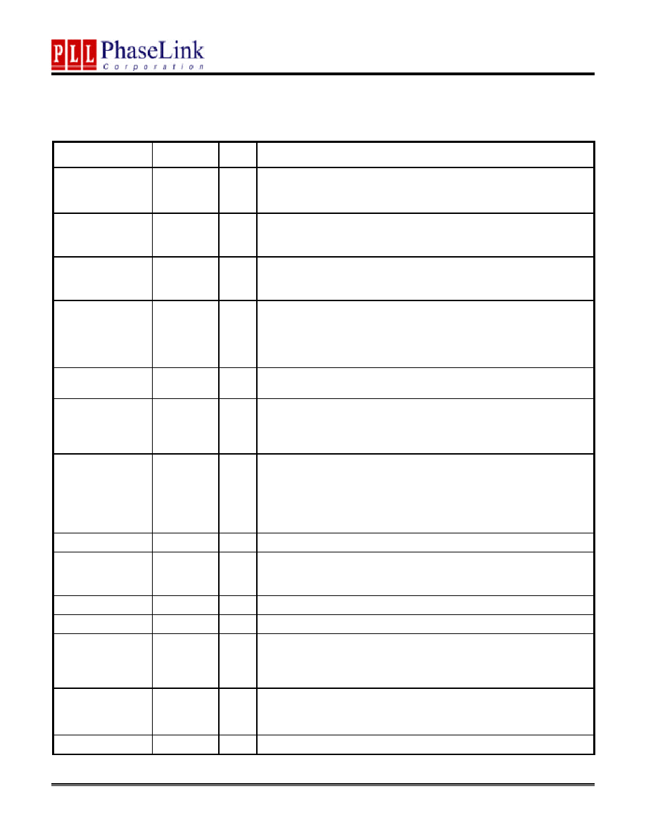
PIN DESCRIPTIONS
Name
Number Type
Description
XIN
3
I
14.318Mhz crystal input to be connected to one end of the crystal
XOUT
4
O
14.318Mhz crystal output
REF0/FS0
1
B
14.318Mhz Reference clock output. This pin latch FS0 value at power-up.
(See Frequency Selection table). It has an internal pull up resistor and 20
ohm on-chip series resistor.
REF1/Vtt_PWRGD#
56
B
If SEL_K7_P4 = 1 (P4 mode), this 3.3V LVTTL input is a level sensitive
strobe at power up used to determine when FS (0:3) and MULT_SEL1
inputs are valid and all outputs are enable when input is transited to a logic
low. If SEL_K7_P4 = 0 (K7 mode), this input is ignored.
This REF1 has I2C programmable double drive strength and it has a 20
ohm on-chip series resistor.
DDRT[0:5]/
SDRAM[0,2,4,6,8,10]
44,42,38,
36,32,30
O
In VIA Mode:
If SEL_SDR_DDR=0, these outputs provide DDR clock outputs, copies
of BUFIN signals;
If SEL_SDR_DDR=1, these outputs provide SDRAM clock outputs,
copies of BUFIN signals.
In ALI_SIS Mode:
If SEL_SDR_DDR=0, these outputs provide DDR clock outputs
generating from internal PLL.
If SEL_SDR_DDR=1, these outputs provide SDRAM clock outputs
generating from internal PLL
DDRC[0:5]/
SD[1,3,5,7,9,11]
43,41,37,
35,31,29
O
In VIA Mode:
If SEL_SDR_DDR=0, these outputs provide DDR clock outputs,
complementary copies of BUFIN signals;
If SEL_SDR_DDR=1, these outputs provide SDRAM clock outputs,
copies of BUFIN signals.
In ALI_SIS Mode:
If SEL_SDR_DDR=0, these outputs provide DDR clock outputs
generating from internal PLL.
If SEL_SDR_DDR=1, these outputs provide SDRAM clock outputs
generating from internal PLL
AGP1/SEL_K7_P4
7
B
This pin latches SEL_K7_P4 value at power-up. After power-up, the pin
acts as AGP1 clock output. When SEL_K7_P4=1, it sets to P4 mode.
SEL_K7_P4=0 in K7 mode. This pin has an internal pull-down resistor and a
20 ohm on-chip series resistor.
PCI1/MULTSEL
12
I/O
This pin latches the MULTSEL value at power-up. After power-up, this pin
acts as PCI2 clock output. MULTSEL is used to select the current multiplier
for the CPU outputs. This pin has a 20 ohm on-chip series resistor.
If MULTSEL=0, IOH=4XIREF.
If MULTSEL=1, IOH=6XIREF
PRELIMINARY
PLL202-151
Programmable Clock Generator for VIA, ALI and SIS DDR SYSTEM
47745 Fremont Blvd., Fremont, California 94538 TEL (510) 492-0990 FAX (510) 492-0991 Rev 11/05/01 Page 3
PIN DESCRIPTIONS (Continue)
Name
Number Type
Description
CPU[T,C]/
CPU0D_[T,C]
52,53
O
In P4 mode, these two pins are differential signals of CPUT and CPUC
In K7 mode, these two pins are differential open drain outputs of CPUODT
and CPUODC.
PCI_F/FS1
10
B
Bi-directional pin. At power-up, the FS1 input value is latched. After
power-up, this pin acts as PCI_F output. It has an internal pull-down and a
20 ohm on-chip series resistor.
48MHz/FS3
20
B
Bi-directional pin. At power-up, the FS3 input value is latched. After
power-up, this pin acts as 48MHz output. It has an internal pull-down and
a 20 ohm on-chip series resistor.
PCI0/
SEL_SDR_DDR
11
B
Bi-directional pin. At power-up, the SEL_SDR_DDR input value is latched.
After power-up, this pin acts as PCI0 output. It has an internal pull-down
and a 20 ohm on-chip series resistor.
If SEL_SDR_DDR=0, DDR mode is selected
If SEL_SDR_DDR=1, SDRAM mode is selected.
PCI[2:5]
14,15,17,18
O
PCI clock output (see Frequency table) with a 20 ohm on-chip series
resistor. PCI5 has I2C programmable double drive strength.
24_48MHz/FS2
21
B
Bi-directional pin. At power-up, the FS2 input value is latched. After
power-up, this pin acts as 24_48MHz output. It has an internal pull-up and
a 20 ohm on-chip series resistor. The selection of 24_48MHz is via I2C on
Byte3 bit6. It will generate 48MHz as power on default.
AGP0_ZCLK/SEL_V
IA
6
B
Bi-directional pin. At power-up, the SEL_VIA input value is latched. After
power-up, this pin acts as AGP0_ZCLK clock output. It has an internal
pull-down and a 20 ohm on-chip series resistor with I2C programmable
double drive strength.
If SEL_VIA=0, VIA mode is selected.
If SEL_VIA=1, ALI_SIS mode is selected.
AGP2
8
O
AGP2 clock output. It has a 20 ohm on-chip series resistor.
Iref
25
I
This pin establishes the reference current for the CPU differential pairs, it
requires a fixed precision resistor tied to ground in order to establish the
appropriate current.
SDATA
28
B
Serial data inputs for serial interface port.
SCLK
27
I
Serial data inputs for serial interface port.
SD#//WDRESET#
26
B
When Byte 10 bit 7 is 1, this pin generates Watchdog timer reset signal
after timer expires. By default, this input pin acts as Slow Down function to
smoothly reduce output frequency by 15~30% depends on internal VCO
divider when SD#=0.
BUF_IN
45
I
In VIA mode, 3.3V CMOS input for SDRAM mode; 2.5V input for DDR
mode.
In ALI_SIS mode, this input should be connected to ground.
FB_OUT
46
O
Feedback clock for chipset. Output voltage depends on VDDD.

PRELIMINARY
PLL202-151
Programmable Clock Generator for VIA, ALI and SIS DDR SYSTEM
47745 Fremont Blvd., Fremont, California 94538 TEL (510) 492-0990 FAX (510) 492-0991 Rev 11/05/01 Page 4
PIN DESCRIPTIONS (Continue)
Name
Number Type
Description
VDDPCI
16
P
3.3V Power Supply for PCIF, PCI[1:6] clock
VDDAGP
5
P
3.3V Power Supply for AGP clock.
VDD48M
22
P
3.3V Power Supply for 48MHz and 24_48MHz clock
VDD
55
P
3.3V power for internal PLL and REF outputs.
VDD1
23
P
3.3V power for I2C Inputs.
VDDCPU_2_5
50
P
2.5v power supply for CPUCS_[T,C] clocks.
VDDCPU_3_3
51
P
3.3v power supply for CPU[T,C]/CPUOD_[T,C] clocks.
VDDD
34,40
P
If SEL_SDR_DDR=0 supply DDR at 2.5V, If SELSDR_DDR=1 supply
SDRAM at 3.3V
VSS
9,13,54,33,
39,19,47,24
P
Ground.
HOST SWING SELECT FUNCTIONS
MULTISEL0
Board Target
Trace/Term Z
Reference R (Rr)
I
ref
= VDD/(3*Rr)
Output Current
V
o h
@ Z
0
50
Rr = 221
; 1%
Iref = 5.0mA
I
oh
= 4*IREF
1.0V @ 50
1
50
Rr = 475
; 1%
Iref = 2.32 mA
I
oh
= 6*IREF
0.7V @ 50
PRELIMINARY
PLL202-151
Programmable Clock Generator for VIA, ALI and SIS DDR SYSTEM
47745 Fremont Blvd., Fremont, California 94538 TEL (510) 492-0990 FAX (510) 492-0991 Rev 11/05/01 Page 5
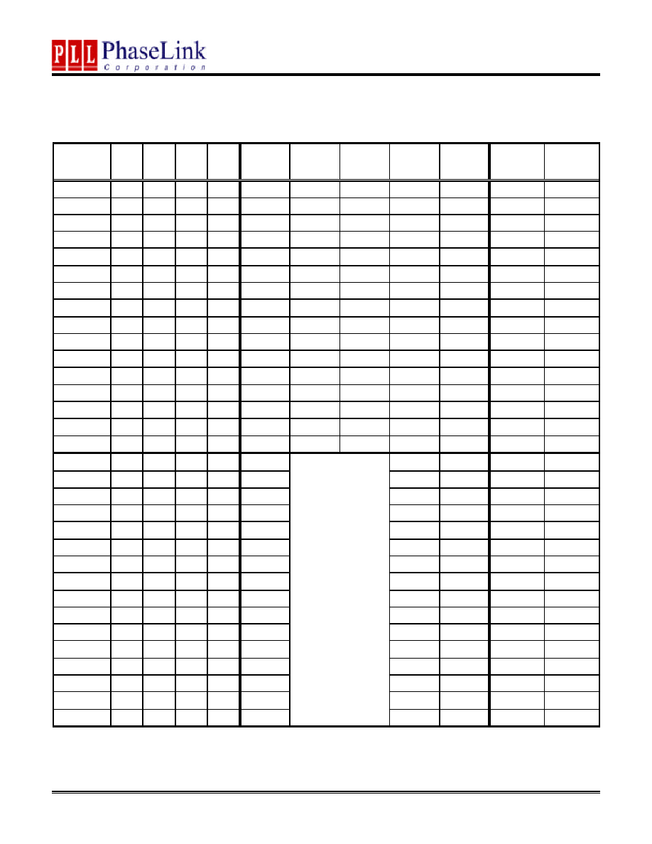
FREQUENCY (MHz) SELECTION TAB LE
SEL_VIA
Mode
FS3 FS2 FS1 FS0 CPU
DDR
SDRAM ZCLK
AGP
PCI
VCO
N
0
0
0
0
0
66.7
66.7
66.7
66.7
33.3
400
28,609
0
0
0
0
1
100
100
66.7
66.7
33.3
400
28,607
0
0
0
1
0
100
100
80
66.7
33.3
400
28,607
0
0
0
1
1
100
133.3
66.7
66.7
33.3
400
28,607
0
0
1
0
0
100
133.3
80
66.7
33.3
400
28,607
0
0
1
0
1
100
160
66.7
66.7
33.3
800
57,214
0
0
1
1
0
100
166.7
62.5
62.5
31.3
500
35,759
0
0
1
1
1
100
166.7
71.4
83.3
41.7
500
35,759
0
1
0
0
0
100
166.7
83.3
62.5
31.3
500
35,759
0
1
0
0
1
100.9
134.5
67.3
67.3
33.6
403.6
28,865
0
1
0
1
0
105
140
70
70
35
420
30,038
0
1
0
1
1
133.3
100
66.7
66.7
33.3
400
28,607
0
1
1
0
0
133.3
133.3
66.7
66.7
33.3
800
57,213
0
1
1
0
1
133.3
160
80
66.7
33.3
800
57,213
0
1
1
1
0
133.3
160
100
66.7
33.3
800
57,213
0
1
1
1
1
133.3
166.7
66.7
66.7
33.3
666.6
47,678
1
0
0
0
0
160
80
40
640
45,772
1
0
0
0
1
164
82
41
656
46,916
1
0
0
1
0
166.6
66.6
33.3
333.3
23,840
1
0
0
1
1
170
68
34
340
24,316
1
0
1
0
0
175
70
35
350
25,032
1
0
1
0
1
180
72
36
360
25,747
1
0
1
1
0
185
74
37
370
26,462
1
0
1
1
1
190
76
38
380
27,177
1
1
0
0
0
111
74
37
444
31,754
1
1
0
0
1
120
80
40
480
34,329
1
1
0
1
0
144
72
36
576
41,195
1
1
0
1
1
156
78
39
624
44,627
1
1
1
0
0
66.6
66.6
33.3
533
38,145
1
1
1
0
1
100
66.6
33.3
400
28,607
1
1
1
1
0
200
66.6
33.3
400
28,607
1
1
1
1
1
133.3
N/A
66.6
33.3
533
38,142
Note: SEL_VIA available through jumper setting only