 | –≠–ª–µ–∫—Ç—Ä–æ–Ω–Ω—ã–π –∫–æ–º–ø–æ–Ω–µ–Ω—Ç: PLL210-01 | –°–∫–∞—á–∞—Ç—å:  PDF PDF  ZIP ZIP |

Advanced information
PLL210-01
Power PC Clock Generator with Integrated 0-delay Buffer for Printer
FEATURES
∑ 1 CPU Clock output with selectable frequencies (33,
50, 66, 83, 100, 133or 166 MHz).
∑ 2 ASIC output clocks (at CPU speed).
∑ 4 PCI output clocks.
∑ Output buffer enable/disable ability for PCI and
BUFOUT.
∑ Selectable Spread Spectrum (SST) for EMI reduction
on ASIC, CPU and PCI.
∑ Advanced, low power, sub-micron CMOS processes.
∑ 14.31818MHz fundamental crystal input.
∑ Low EMI Spread Spectrum Technology is available for
the CPU, ASIC and PCI clock.
∑ Support I2C serial interface
∑
Available in 48-Pin SSOP
FREQUENCY TABLES
OE_BUF4_5^
OE_PCI0^
VDDOSC
PCI1/FS1*
VSSPCI
OE_BUF6_7^
VSSOSC
PCIS^
OE_BUF0_1^
OE_BUF2_3^
VSSA2
BUFOUT0
VDDCPU
BUFOUT7
VDDASIC
ASIC0
BUFOUT1
VSSBUF
BUFOUT2
VSSBUF
VDDBUF
BUFOUT5
BUFOUT6
ASIC1
XIN
XOUT
CPU
BUFIN
BUFOUT3
SDATA
PWRGD/RB
VDDA2
PLL210-01
1
2
3
4
5
6
7
8
9
10
11
12
13
14
15
16
17
18
19
20
21
22
23
24
40
39
38
37
36
35
34
33
32
31
30
29
28
27
26
25
41
42
44
43
45
46
47
48
OE_PCI3^
OE_PCI2^
VSS
PCI3/SSC1^
VDDA1
OE_PCI1^
SCLK
FS2
PCI0/FS0*
VDDPCI
VSSA1
PCI2/SSC0^
VSSASIC
VDDBUF
VSSCPU
BUFOUT4
PIN ASSIGNMENT
Note: ^: Internal pull-up resistor *: Bi-directional pin
FS2
FS1
FS0 CPU
ASIC(0:1)
0
0
0
33.3 MHz
33.3 MHz
0
0
1
50.0 MHz
50.0 MHz
0
1
0
66.6 MHz
66.6 MHz
0
1
1
83.3 MHz
83.3 MHz
1
0
0
100.0 MHz
100.0 MHz
1
0
1
133.3 MHz
133.3 MHz
1
1
1
166.6 MHz
166.6 MHz
SPREAD SPECTRUM SELECTION TABLE
PCIS PCI
(0:3)
0 33.3
MHz
1 66.6
MHz
KEY SPECIFICATIONS
∑ CPU Output Jitter < 120ps
∑ ASIC Output Jitter < 150ps
∑
PCI Output Jitter < 250ps
∑ BUFOUT Output Jitter < 250ps
∑ ASIC-ASIC Skew < 250ps
∑ PCI-PCI Skew < 250ps
∑ BUFOUT-BUFOUT Skew < 100ps
∑ CPU-ASIC-PCI Skew < 250ps
∑
ASIC-PCI Skew < 250ps
POWER GROUP
∑ VDDOSC, VSSOSC: XIN, XOUT
∑ VDDPCI, VSSPCI: PCI
∑ VDDA, VSSA: PLL CORE
∑ VDDBUF, VSSBUF: BUFOUT (0:7)
∑ VDDASIC, VSSASIC: ASIC (0:1)
∑
VDDCPU, VSSCPU: CPU
SSC1
SSC0
Spread Spectrum Modulation
0
0
OFF
0
1
- 0.50% ≠ Downspread
1
0
- 1.00% ≠ Downspread
1
1
- 1.50% ≠ Downspread
47745 Fremont Blvd., Fremont, California 94538 TEL (510) 492-0990 FAX (510) 492-0991 08/28/03 Page 1
Advanced information
PLL210-01
Power PC Clock Generator with Integrated 0-delay Buffer for Printer
Note: When CPU=133.3 MHz, it implements 130.9 MHz to meet Power PC clock AC Timing Specification; when CPU=150.0 MHz, it implements 148.1
MHz to meet Power PC clock AC Timing Specification; when CPU=166.6 MHz, it implements 162.6 MHz to meet Power PC clock AC Timing
Specification.
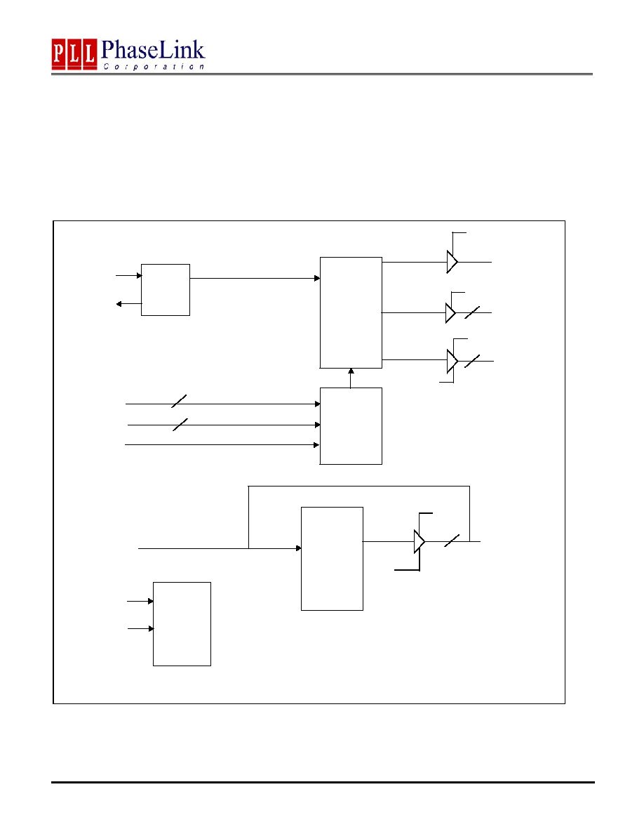
BLOCK DIAGRAM
Control
Logic
PLL1
SST
X tal
OSC
SSC(0:1)
XIN
XOUT
2
ASIC(0:1)
PCI(0:3)
PCIS
2
14.318MHz
2
4
CPU
VDDASIC
VDDPCI
I2C
Control
SCLK
SDATA
PLL2
Zero delay
8
BUFOUT(0:7)
VDDBUF
BUFIN
VDDCPU
FS(0:1)
OE_BUF(0:7)
OE_PCI(0:3)
47745 Fremont Blvd., Fremont, California 94538 TEL (510) 492-0990 FAX (510) 492-0991 08/28/03 Page 2

Advanced information
PLL210-01
Power PC Clock Generator with Integrated 0-delay Buffer for Printer
PIN DESCRIPTIONS
Name Number
Type
Description
VDD
2,5,11, 29,
38,39,44,45
P Power
supply
VSS
1,6,14,30,17
34,40,41,47
P Ground
XIN/XOUT 3,4
B
Crystal input to be connected to a 14.31818MHz fundamental crystal
(CL = 20pF, parallel resonant mode). Load capacitors have been
integrated on the chip. No external load capacitor is required.
SSC (0:1)
12,13
I
Bi-level input for SST control (see Spread Spectrum selection table on
p.4). `0' = 10k
pull down, `1' (default, internal pull up) = Not
connected.
OE_PCI(0:3) 15,16,18,19
I
Output enable pin for PCI output clocks, `1' (default, internal pull up) =
enable, `0' = disable
OE_BUF(0:7) 20,21,22,23 I
Output enable pin for BUFFER output clocks, `1' (default, internal pull
up) = enable, `0' = disable
PCIS 7
I
the value of PCIS is latched in and used to select the PCI clock output
(see frequency table on p.1). When PCIS = `0', PCI clock will be
33.3MHz, and 66.6MHz if PCIS = `1'.
SCLK/SDATA
24,25
B
Serial data input for I2C serial interface port (internal pull up)
FS(0:1) 9,10
B
Tri-level frequency selection input pin, `0' = 10k
pull down, `1' =
10k
pull up, M (default) = not connected
BUFIN
37
I
Zero delay buffer clock input pin
BUFOUT(0:7)
26,27,28,31,
32,33,35,36
O
Zero delay buffer output pin
PCI (0:3)
9,10,12,13
O
PCI clocks signal output pin
ASIC (0:1)
42,43
O
ASIC clocks signal output pins, will have the same frequency as CPU.
(see frequency table on p.1).
PWRGD/RB 48
I
At power-up, this pin works as PWRGD. Before power supply
stabilized, the input of PWRGD should be low, PLL loop and all output
is disabled. After power supply stabilized, PWRGD change to high,
FS(0:1), SSC(0:1) are latched and PLL loop is enabled, later on, the
output buffers is enabled as well. After power-up, this pin works as
Reset pin, when low, all the circuit will be reset.
CPU 46
O
CPU clock signal output pin. The CPU clock frequency is selected as
per the frequency table on page 1, depending on the value of FS(0:1).
47745 Fremont Blvd., Fremont, California 94538 TEL (510) 492-0990 FAX (510) 492-0991 08/28/03 Page 3
Advanced information
PLL210-01
Power PC Clock Generator with Integrated 0-delay Buffer for Printer
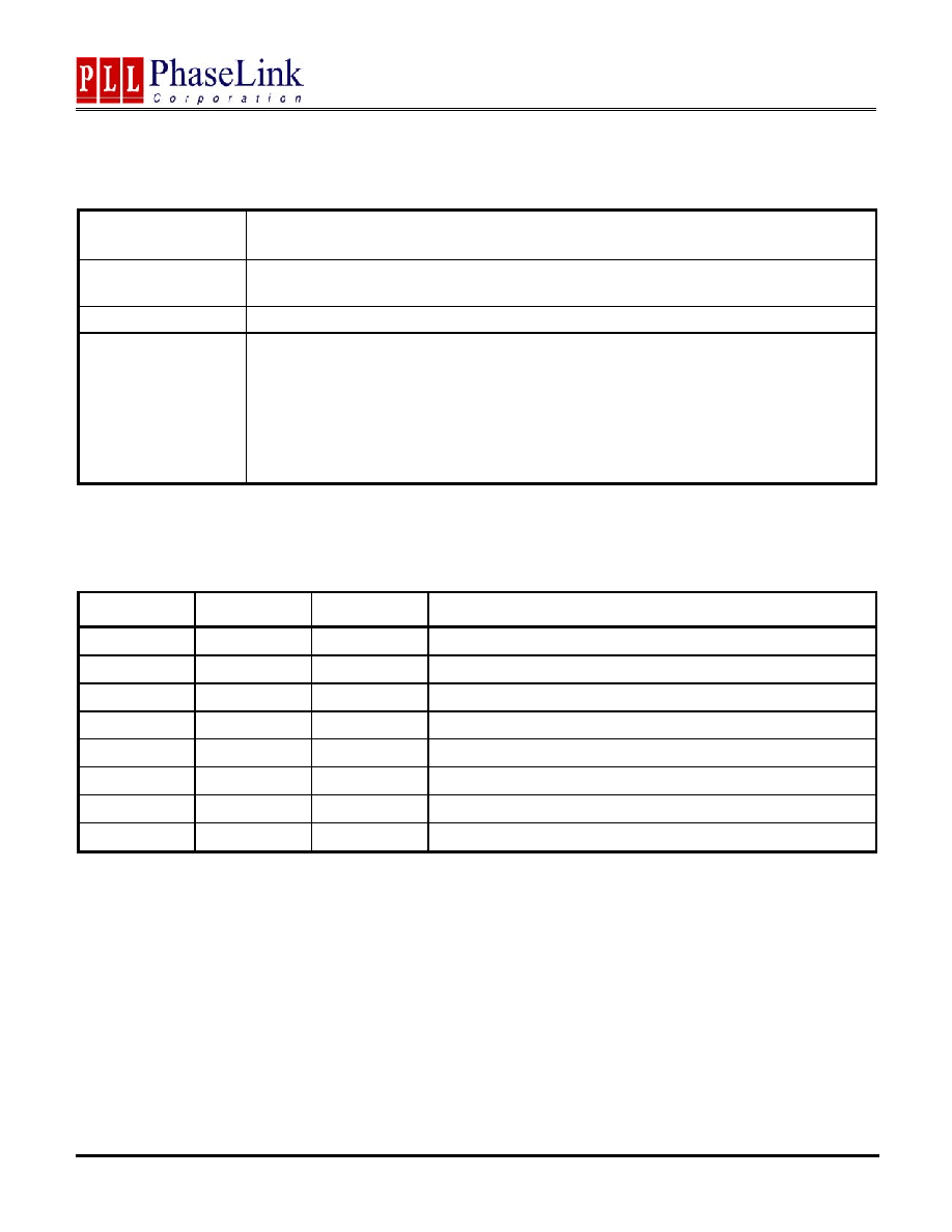
I2C BUS CONFIGURATION SETTING
Address Assignment
A6 A5 A4 A3 A2 A1 A0 R/W
1 1 0 1 0 0 1 _
Slave
Receiver/Transmitter
Provides both slave write and readback functionality
Data Transfer Rate
Standard mode at 100kbits/s
Data Protocol
This serial protocol is designed to allow both blocks to write and read from the controller. The
bytes must be accessed in sequential order from lowest to highest bytes. Each byte
transferred must be followed by 1 acknowledge bit. A byte transferred without acknowledged
bit will terminate the transfer. The write or read block both begins with the master sending a
slave address and a write condition (0XD2) or a read condition (0xD3).
Command Byte and Byte Count Byte must be sent by the master but ignored by the slave, in Read Mode:
the Byte Count Byte will be read by the master then all other Data Byte. Byte Count Byte default at power-
up is = ( 0 x 09 )
I2C CONTROL REGISTERS
1. BYTE 0: Output Register (1=Enable, 0=Disable)
Bit Pin#
Default
Description
Bit 7
32
1
BUFOUT7 (1=Active 0=Inactive)
Bit 6
31
1
BUFOUT6 (1=Active 0=Inactive)
Bit 5
30
1
BUFOUT5 (1=Active, 0=Inactive)
Bit 4
29
1
BUFOUT4 (1=Active, 0=Inactive)
Bit 3
26
1
BUFOUT3 (1=Active, 0=Inactive)
Bit 2
25
1
BUFOUT2 (1=Active, 0=Inactive)
Bit 1
24
1
BUFOUT1 (1=Active, 0=Inactive)
Bit 0
23
1
BUFOUT0 (1=Active, 0=Inactive)
47745 Fremont Blvd., Fremont, California 94538 TEL (510) 492-0990 FAX (510) 492-0991 08/28/03 Page 4

Advanced information
PLL210-01
Power PC Clock Generator with Integrated 0-delay Buffer for Printer
2. BYTE 1: Output Register (1=Enable, 0=Disable)
Bit Pin#
Default
Description
Bit 7
-
-
-
Bit 6
47
1
CPU (1=Active, 0=Inactive)
Bit 5
44
1
ASIC 1 (1=Active, 0=Inactive)
Bit 4
43
1
ASIC 0 (1=Active, 0=Inactive)
Bit 3
40
1
PCI 3 (1=Active, 0=Inactive)
Bit 2
39
1
PCI 2 (1=Active, 0=Inactive)
Bit 1
38
1
PCI 1 (1=Active, 0=Inactive)
Bit 0
37
1
PCI 0 (1=Active, 0=Inactive)
FUNCTIONAL DESCRIPTION
Connecting a bi-directional pin
In order to reduce pin usage, the PLL210-01 uses bi-directional input pins. The same pin serves as input upon power-up, and as
output as soon as the inputs have been latched. The value of the input is latched-in upon power-up. Depending on the pin (see
pin description), the input can be tri-level or a standard two-level. Unlike unidirectional pins, bi-directional pins cannot be
connected directly to GND or VDD in order to set the input to "0" or "1", since the pin also needs to serve as output. In the case
of two level input pins, an internal pull-up resistor is present. This allows a default value to be set when no external pull down
resistor is connected between the pin and GND (by definition, a tri-level input has a the default value of "M" (mid) if it is not
connected). In order to connect a bi-directional pin to a non-default value, the input must be connected to GND or VDD through
an external pull-down/pull-up resistor. Note: when the output load presents a low impedance in comparison to the internal pull-
up resistor, the internal pull-up resistor may not be sufficient to pull the input up to a logical "one", and an external pull-up
resistor may be required.
For bi-directional inputs, the external loading resistor between the pin and GND has to be sufficiently small (compared to the
internal pull-up resistor) so that the pin voltage be pulled below 0.8V (logical "zero"). In order to avoid loading effects when the
pin serves as output, the value of the external pull-down resistor should however be kept as large as possible. In general, it is
recommended to use an external resistor of around one sixth to one quarter of the internal pull-up resistor (see Application
Diagram). Note: when the output is used to drive a load presenting an small resistance between the output pin and VDD, this
resistance is in essence connected in parallel to the internal pull-up resistor. In such a case, the external pull-down resistor may
have to be dimensioned smaller to guarantee that the pin voltage will be low enough achieve the desired logical "zero". This is
particularly true when driving 74FXX TTL components.
47745 Fremont Blvd., Fremont, California 94538 TEL (510) 492-0990 FAX (510) 492-0991 08/28/03 Page 5