 | –≠–ª–µ–∫—Ç—Ä–æ–Ω–Ω—ã–π –∫–æ–º–ø–æ–Ω–µ–Ω—Ç: PLL521-23 | –°–∫–∞—á–∞—Ç—å:  PDF PDF  ZIP ZIP |

PLL521-23
Low Phase Noise PECL VCXO (100MHz to 200MHz)
47745 Fremont Blvd., Fremont, California 94538 TEL (510) 492-0990 FAX (510) 492-0991 Rev 05/19/05 Page 1
FEATURES
∑ 100MHz to 200MHz Fundamental Mode Crystal.
∑ Output range: 100MHz ≠ 200MHz.
∑ Complementary PECL outputs.
∑ Selectable OE Logic (enable high or enable low).
∑ Integrated variable capacitors.
∑ High pull linearity: < 5%.
∑ +/- 120 ppm pull range
∑ Supports 2.5V or 3.3V-Power Supply.
∑ Available in 16-pinTSSOP and die form.
∑ Thickness 10 mil.
DESCRIPTION
PLL521-23 is a VCXO IC specifically designed to
pull high frequency fundamental crystals. Its internal
varicaps allow an on chip frequency pulling,
controlled by the VCON input. The chip provides a
low phase noise, low jitter PECL differential clock
output.
BLOCK DIAGRAM
DIE SPECIFICATIONS
Name Value
Size
56.5 x 57.5 mil
Reverse side
GND
Pad dimensions
80 micron x 80 micron
Thickness 10
mil
DIE CONFIGURATION
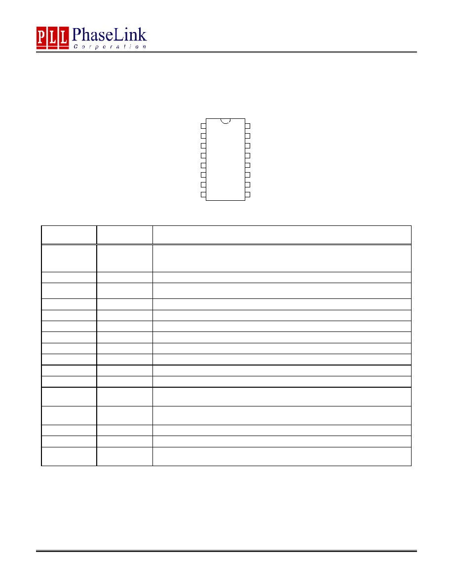
PACKAGE CONFIGURATION
OUTPUT ENABLE LOGIC SELECTION
OESEL*
(Pad/Pin #14)
OECTRL*
(Pad #22, Pin # 6)
State
0 (Default)
Output enabled
0 (Default)
1 Tri-state
0 Tri-state
1
1 (Default)
Output enabled
* Bond to GND to set to "0", bond to VDD to set to "1". No connection results
to "default" setting through internal pull-up/-down.
Pad #22, Pin #6: Logical states defined by PECL V
I H
and V
I L
levels.
HIGH IMPEDANCE BUFFER LOGIC
SELECTION
BUFZSEL
(Pad/Pin #15)
State
0 (Default)
Hi Z if Output is Disabled
1
(Q=0) +(Qbar=1) if Output Disabled
18
21
Y
X
(0,0)
(1460,1435)
56
.
5
mi
l
57.5 mil
19
20
22
1
2
3
4
6
13
14
11
17
16
15
12
10
9
8
7
5
GNDBUF
PECL
PECLBAR
VDDBUF
VDDBUF
VDDANA
OECTRL
XOUT
XIN
VCON
GNDOSC
G
NDB
U
F
GNDANA
GNDOS
C
VCO
N
GNDANA
N/
C
VDDO
S
C
OS
C
O
FF
OE
S
E
L
V
G
NDB
U
F
BUFZSEL
Die ID: 560A-EEEE-ER
X+
X-
OE
Q
PLL521-23
VCON
Q
Oscillator
Amplifier
w/
integrated
varicaps

PLL521-23
Low Phase Noise PECL VCXO (100MHz to 200MHz)
47745 Fremont Blvd., Fremont, California 94538 TEL (510) 492-0990 FAX (510) 492-0991 Rev 05/19/05 Page 2
PAD ASSIGNMENT AND DESCRIPTION
Die Pad
Name
Pad #
X (
µm) Y
(
µm)
Description
VCON
1
329.6 110.1
Control Voltage input. Use this pin to change the
output frequency by varying the applied Control
Voltage.
GNDOSC 2 498.3 110.0
GND connection for oscillator circuitry.
GNDANA 3 696.2 110.0
GND connection for analog circuitry.
GNDANA 4 825.0 110.0
GND connection for analog circuitry.
GNDBUF 5 973.6 110.0
GND connection for output buffer circuitry.
GNDBUF 6 1150.0 109.1
GND connection for output buffer circuitry.
GNDBUF
(optional)
7
1183.6 302.2
GND connection for output buffer circuitry.
PECL 8
1183.6 452.3
PECL output
PECLBAR 9 1183.6 613.5
PECL complementary output.
VDDBUF
(optional)
10
1182.4 745.9
VDD connection for output buffer circuitry.
VDDBUF should be separately decoupled from other
VDDs whenever possible.
VDDBUF 11 1252.4 903.6
VDD connection for output buffer circuitry.
VDDBUF should be separately decoupled from other
VDDs whenever possible.
VDDANA 12 1252.4 1081.3
VDD connection for analog circuitry.
VDDANA should be separately decoupled from other
VDDs whenever possible.
DNC 13
1058.5 1221.6
Do Not Connect
OESEL 14 864.5 1221.6
Selector input to choose the OE control logic. See
table on page 1.
BUFZSEL 15 624.0 1222.6
Output impedance selector
VDDOSC 16 467.1 1222.7
VDD connection for oscillator circuitry.
VDDOSC should be separately decoupled from other
VDDs whenever possible.
OSCOFF 17 271.1 1222.6
Oscillator Off Selection input pad. When low, turns
off the oscillator when output is disabled. When high
(default), oscillator running when output is disabled.
Internal pull-up
GNDOSC
(optional)
18
109.4
1222.9
GND connection for oscillator circuitry.
VCON 19 108.9 1062.1
Control Voltage input. Use this pin to change the
output frequency by varying the applied Control
Voltage (internally connected to pad 1).
XIN 20
109.0
865.8
Crystal oscillator input pad.
XOUT 21 108.6
358.4
Crystal oscillator output pad.
OECTRL 22 108.6
146.5
OE input pad. See table on page 1.
Note: for optimal Phase Noise performance, it is recommended to bond all optional VDD and GND pads.
PLL521-23
Low Phase Noise PECL VCXO (100MHz to 200MHz)
47745 Fremont Blvd., Fremont, California 94538 TEL (510) 492-0990 FAX (510) 492-0991 Rev 05/19/05 Page 3
PACKAGE
PIN ASSIGNMENT AND DESCRIPTION
OSCOFFSEL
GNDOSC
VCON
XIN
XOUT
OECTRL
DNC
GND
VDDOSC
BUFZSEL
OESEL
VDDANA
VDDBUF
QBAR
Q
GND
1
2
3
4
5
6
7
8
9
10
11
12
13
14
15
16
PLL52
1-23
Pin #
Name
Description
1 OSCOFFSEL
Oscillator Off Selection input pad. When low, turns off the oscillator when output is
disabled. When high (default), oscillator running when output is disabled.
Internal pull-up
2
GNDOSC
GND connection for oscillator circuitry.
3 VCON
Control Voltage input. Use this pin to change the output frequency by varying the applied
Control Voltage.
4
XIN
Crystal oscillator input pin.
5 XOUT
Crystal oscillator output pin.
6
OECTRL
OE input pad. See table on page 1.
7
DNC
Do Not Connect.
8
GND
Ground connection.
9 GND
Ground
connection.
10
Q PECL
Output.
11
QBAR PECL
complementary
output.
12 VDDBUF
VDD connection for output buffer circuitry.
VDDBUF should be separately decoupled from other VDDs whenever possible.
13 VDDANA
VDD connection for analog circuitry.
VDDANA should be separately decoupled from other VDDs whenever possible.
14
OESEL
Selector input to choose the OE control logic. See table on page 1.
15
BUFZSEL
Output impedance selector
16 VDDOSC
VDD connection for oscillator circuitry.
VDDOSC should be separately decoupled from other VDDs whenever possible.
PLL521-23
Low Phase Noise PECL VCXO (100MHz to 200MHz)
47745 Fremont Blvd., Fremont, California 94538 TEL (510) 492-0990 FAX (510) 492-0991 Rev 05/19/05 Page 4
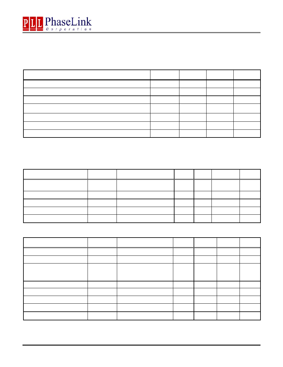
ELECTRICAL SPECIFICATIONS
1. Absolute Maximum Ratings
PARAMETERS SYMBOL
MIN.
MAX.
UNITS
Supply Voltage
V
DD
4.6 V
Input Voltage, dc
V
I
V
SS
-0.5 V
DD
+0.5 V
Output Voltage, dc
V
O
V
SS
-0.5 V
DD
+0.5 V
Storage Temperature
T
S
-65 150
∞C
Ambient Operating Temperature
T
A
-45 85
∞C
Junction Temperature
T
J
125
∞C
Input Static Discharge Voltage Protection
2
kV
Exposure of the device under conditions beyond the limits specified by Maximum Ratings for extended periods may cause permanent damage to the
device and affect product reliability. These conditions represent a stress rating only, and functional operations of the device at these or any other
conditions above the operational limits noted in this specification is not implied.
2. Crystal Specifications
PARAMETERS SYMBOL CONDITIONS MIN.
TYP.
MAX.
UNITS
Crystal Resonator Frequency
F
XIN
Parallel Fundamental Mode
100
200
MHz
Crystal Loading Rating
C
L (xtal)
Die at VCON = 1.65V
5.0
pF
Interelectrode Capacitance
C
0
3.5
pF
Crystal Pullability
C
0
/C
1 (xtal)
AT cut
350 -
Recommended ESR
R
E
AT cut
30
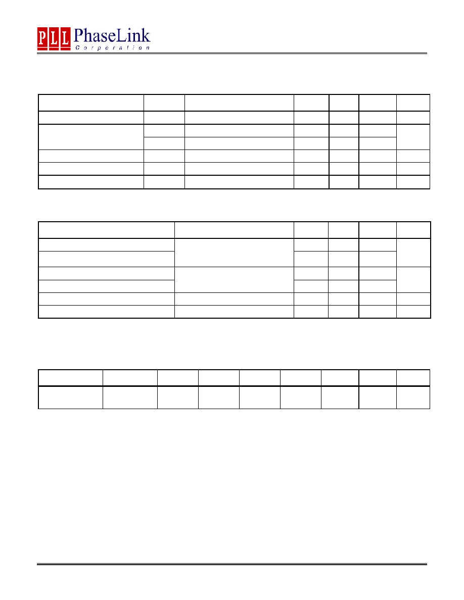
3. Voltage Control Crystal Oscillator
PARAMETERS SYMBOL CONDITIONS MIN.
TYP.
MAX.
UNITS
VCXO Stabilization Time
T
VCXOSTB
From
power
valid
10
ms
VCXO Tuning Range
XTAL C
0
/C
1
< 350
250
ppm
CLK output pullability
0V
VCON 3.3V
at room temperature
XTAL C
0
/C
1
= 350
±120
ppm
On-chip Varicaps control range
VCON = 0 to 3.3V
3.3 ≠ 8.8
pF
Linearity
5
%
VCXO Tuning Characteristic
75
ppm/V
VCON input impedance
2000
k
VCON modulation BW
0V
VCON 3.3V, -3dB
25
kHz
PLL521-23
Low Phase Noise PECL VCXO (100MHz to 200MHz)
47745 Fremont Blvd., Fremont, California 94538 TEL (510) 492-0990 FAX (510) 492-0991 Rev 05/19/05 Page 5
4. General Electrical Specifications
PARAMETERS SYMBOL CONDITIONS MIN.
TYP.
MAX.
UNITS
Supply Current (Loaded Outputs)
I
DD
at 3.3V @ 155MHz
55
mA
Oscillator
off
10
Output valid after OE enabled
Oscillator
on
0.0001
ms
Operating Voltage
V
DD
2.25
3.63
V
Output Clock Duty Cycle
@ Vdd ≠ 1.3V (PECL)
45
50
55
%
Short Circuit Current
±50
mA
5. Jitter specifications
PARAMETERS CONDITIONS
MIN.
TYP.
MAX.
UNITS
Period jitter RMS at 155MHz
2.0
Period jitter peak-to-peak at 155MHz
At 155.52MHz, with capacitive
decoupling between VDD and GND.
Over 10,000 cycles
15
20
ps
Accumulated jitter RMS at 155MHz
2.0
Accumulated jitter peak-to-peak at 155MHz
At 155.52MHz, with capacitive
decoupling between VDD and GND.
Over 1,000,000 cycles.
20
25
ps
Random Jitter
"RJ" measured on Wavecrest SIA 3000
2.0
ps
Integrated jitter RMS at 155MHz
Integrated 12 kHz to 20 MHz
0.25
0.35 ps
Measured on Wavecrest SIA 3000
6. Phase noise specifications
PARAMETERS FREQUENCY 10Hz
100Hz 1kHz 10kHz
100kHz
1MHz
UNITS
Phase Noise
relative to carrier
155.52MHz -70 -100 -130 -145 -145 -150
dBc/Hz
Note: Phase Noise measured at VCON = 0V