Specifications are subject to change without notice.
70
MARCH 1994 - REVISED OCTOBER 2000
TISP3xxxF3 (HV) Overvoltage Protector Series
TISP3240F3, TISP3260F3,
TISP3290F3,TISP3320F3,TISP3380F3
HIGH-VOLTAGE DUAL BIDIRECTIONAL THYRISTOR
OVERVOLTAGE PROTECTORS
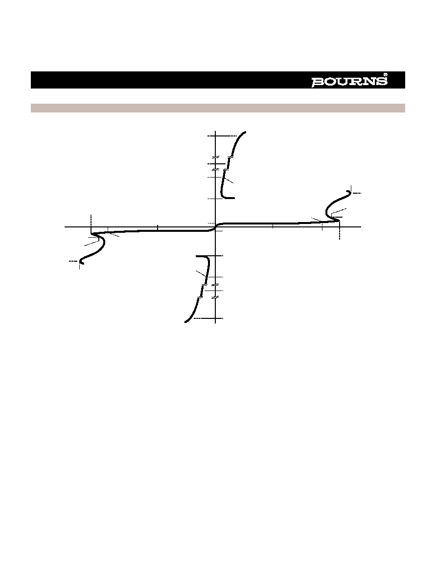
Device Symbol
SL Package (Top View)
P Package (Top View)
Ion-Implanted Breakdown Region
Precise and Stable Voltage
Low Voltage Overshoot under Surge
Planar Passivated Junctions
Low Off-State Current <10
µA
Rated for International Surge Wave Shapes
How To Order
D Package (Top View)
Description
These high-voltage dual bidirectional thyristor protectors are
designed to protect ground backed ringing central office, access
and customer premise equipment against overvoltages caused by
lightning and a.c. power disturbances. Offered in five voltage
variants to meet battery and protection requirements, they are
guaranteed to suppress and withstand the listed international
lightning surges in both polarities. Overvoltages are initially
clipped by breakdown clamping until the voltage rises to the
breakover level, which causes the device to switch. The high
crowbar holding current prevents d.c. latchup as the current
subsides.
DEVICE
V
DRM
V
V
(BO)
V
`3240F3
180
240
`3260F3
200
260
`3290F3
220
290
`3320F3
240
320
`3380F3
270
380
Waveshape
Standard
I
TSP
A
2/10
µs
GR-1089-CORE
175
8/20
µs
IEC 61000-4-5
120
10/160
µs
FCC Part 68
60
10/700
µs
ITU-T K.20/21
FCC Part 68
50
10/560
µs
FCC Part 68
45
10/1000
µs
GR-1089-CORE
35
1
2
3
4
5
6
7
8
G
G
G
G
NC
T
R
NC
NC - No internal connection
R
G
T
G
T
G
G
R
1
2
3
4
5
6
7
8
Specified T terminal ratings require connection of pins 1 and 8.
Specified R terminal ratings require connection of pins 4 and 5.
MD1XAB
1
2
3
T
G
R
G
T
R
SD3XAA
Terminals T, R and G correspond to the
alternative line designators of A, B and C
Device
Package
Carrier
Order As
TISP3xxxF3
D, Small-outline
Tape And Reeled
TISP3xxxF3DR
P, Plastic Dip
Tube
TISP3xxxF3P
SL, Single-in-line
Tube
TISP3xxxF3SL
Insert xxx value corresponding to protection voltages of 240 through to 380
.............................................. UL Recognized Component

Specifications are subject to change without notice.
71
MARCH 1994 - REVISED OCTOBER 2000
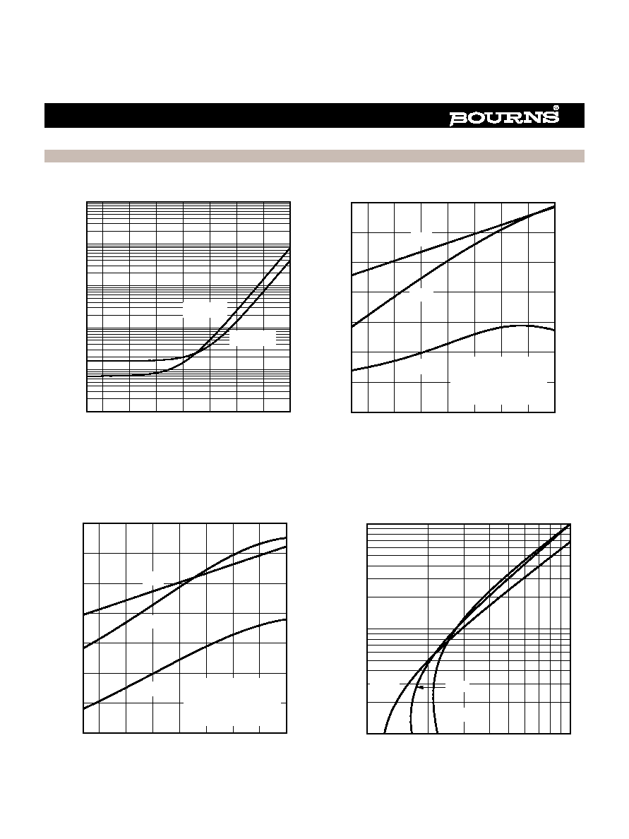
These monolithic protection devices are fabricated in ion implanted planar structures to ensure precise and matched breakover control and are
virtually transparent to the system in normal operation.
Electrical Characteristics for R and T Terminal Pair, TA = 25 ∞C (Unless Otherwise Noted)
Parameter
Test Conditions
Min
Typ
Max
Unit
I
DRM
Repetitive peak off-
state current
V
D
=
±2V
DRM
, 0
∞C < T
A
< 70
∞C
±10
µA
I
D
Off-state current
V
D
=
±50 V
±10
µA
C
off
Off-state capacitance
f = 100 kHz,
V
d
= 100 mV , V
D
= 0,
Third terminal voltage = -50 V to +50 V
(see Notes 4 and 5)
D Package
P Package
SL Package
0.05
0.065
0.03
0.15
0.2
0.1
pF
NOTES: 4. These capacitance measurements employ a three terminal capacitance bridge incorporating a guard circuit. The third terminal is
connected to the guard terminal of the bridge.
5. Further details on capacitance are given in the Applications Information section.
Absolute Maximum Ratings, TA = 25 ∞C (Unless Otherwise Noted)
TISP3xxxF3 (HV) Overvoltage Protector Series
Description (continued)
Rating
Symbol
Value
Unit
Repetitive peak off-state voltage, 0
∞C < T
A
< 70
∞C
`3240F3
`3260F3
`3290F3
`3320F3
`3380F3
V
DRM
±180
±200
±220
±240
±270
V
Non-repetitive peak on-state pulse current (see Notes 1 and 2)
I
PPSM
A
1/2 (Gas tube differential transient, 1/2 voltage wave shape)
350
2/10 (Telcordia GR-1089-CORE, 2/10 voltage wave shape)
175
1/20 (ITU-T K.22, 1.2/50 voltage wave shape, 25
resistor)
90
8/20 (IEC 61000-4-5, combination wave generator, 1.2/50 voltage wave shape)
120
10/160 (FCC Part 68, 10/160 voltage wave shape)
60
4/250 (ITU-T K.20/21, 10/700 voltage wave shape, simultaneous)
55
0.2/310 (CNET I 31-24, 0.5/700 voltage wave shape)
38
5/310 (ITU-T K.20/21, 10/700 voltage wave shape, single)
50
5/320 (FCC Part 68, 9/720 voltage wave shape, single)
50
10/560 (FCC Part 68, 10/560 voltage wave shape)
45
10/1000 (Telcordia GR-1089-CORE, 10/1000 voltage wave shape)
35
Non-repetitive peak on-state current, 0
∞C < T
A
< 70
∞C (see Notes 1 and 3)
50 Hz,
1 s
D Package
P Package
SL Package
I
TSM
4.3
5.7
7.1
A
Initial rate of rise of on-state current,
Linear current ramp, Maximum ramp value < 38 A
di
T
/dt
250
A/
µs
Junction temperature
T
J
-65 to +150
∞C
Storage temperature range
T
stg
-65 to +150
∞C
NOTES: 1. Further details on surge wave shapes are contained in the Applications Information section.
2. Initially, the TISP
Æ
device m ust be in thermal equilibrium with 0
∞C < T
J
<70
∞C. The surge may be repeated after the TISP
Æ
device
returns to its initial conditions.
3. Above 70
∞C, derate linearly to zero at 150 ∞C lead temperature.
Specifications are subject to change without notice.
72
MARCH 1994 - REVISED OCTOBER 2000
Electrical Characteristics for T and G or R and G Terminals, TA = 25 ∞C (Unless Otherwise Noted)
Thermal Characteristics
TISP3xxxF3 (HV) Overvoltage Protector Series
Parameter
Test Conditions
Min
Typ
Max
Unit
R
JA
Junction to free air thermal resistance
P
tot
= 0.8 W, T
A
= 25
∞C
5 cm
2
, FR4 PCB
D Package
160
∞C/W
P Package
100
SL Package
135
Parameter
Test Conditions
Min
Typ
Max
Unit
I
DRM
Repetitive peak off-
state current
V
D
=
±V
DRM
, 0
∞C < T
A
< 70
∞C
±10
µA
V
(BO)
Breakover voltage
dv/dt =
±250 V/ms, R
SOURCE
= 300
`3240F3
`3260F3
`3290F3
`3320F3
`3380F3
±240
±260
±290
±320
±380
V
V
(BO)
Impulse breakover
voltage
dv/dt
±1000 V/µs, Linear voltage ramp,
Maximum ramp value =
±500 V
R
SOURCE
= 50
`3240F3
`3260F3
`3290F3
`3320F3
`3380F3
±267
±287
±317
±347
±407
V
I
(BO)
Breakover current
dv/dt =
±250 V/ms, R
SOURCE
= 300
±0.1
±0.6
A
V
T
On-state voltage
I
T
=
±5 A, t
W
= 100
µs
±3
V
I
H
Holding current
I
T
=
±5 A, di/dt = -/+30 mA/ms
±0.15
A
dv/dt
Critical rate of rise of
off-state voltage
Linear voltage ramp, Maximum ramp value < 0.85V
DRM
±5
kV/
µs
I
D
Off-state current
V
D
=
±50 V
±10
µA
C
off
Off-state capacitance
f = 1 MHz,
V
d
= 0.1 V r.m.s., V
D
= 0
f = 1 MHz,
V
d
= 0.1 V r.m.s., V
D
= -5 V
f = 1 MHz,
V
d
= 0.1 V r.m.s., V
D
= -50 V
(see Notes 5 and 6)
57
26
11
95
45
20
pF
NOTES: 6
These capacitance measurements employ a three terminal capacitance bridge incorporating a guard circuit. The third terminal is
connected to the guard terminal of the bridge.
7. Further details on capacitance are given in the Applications Information section.