2
www.power-one.com
Output 1
Output 2
Type
Type
Options
U
o nom
I
o nom
I
o max
U
o nom
I
o nom
I
o max
Input Voltage
Input Voltage
[V DC]
[A]
[A]
[V DC]
[A]
[A]
43...108 V DC
65...168 V DC
3.3
18
22
-
-
-
DQ 1101-7
EQ 1101-7
-9
5.1
16
20
-
-
-
DQ 1001-7R
EQ 1001-7R
-9, P
12
8
10
-
-
-
DQ 2320-7R
EQ 2320-7R
-9, P
15
6.6
8
-
-
-
DQ 2540-7R
EQ 2540-7R
-9, P
24
4
5.5
-
-
-
DQ 2660-7R
EQ 2660-7R
-9, P
24
4
5
-
-
-
DQ 2320-7R
EQ 2320-7R
-9, P
30
3.3
4
-
-
-
DQ 2540-7R
EQ 2540-7R
-9, P
48
2.2
2.75
-
-
-
DQ 2660-7R
EQ 2660-7R
-9, P
5.1
7.5
9.5
5.1
7.5
9.5
DQ 2001-7R
EQ 2001-7R
-9, P
12
4.4
5
12
4.4
5
DQ 2320-7R
EQ 2320-7R
-9, P
15
3.3
4
15
3.3
4
DQ 2540-7R
EQ 2540-7R
-9, P
24
2.2
2.75
24
2.2
2.75
DQ 2660-7R
EQ 2660-7R
-9, P
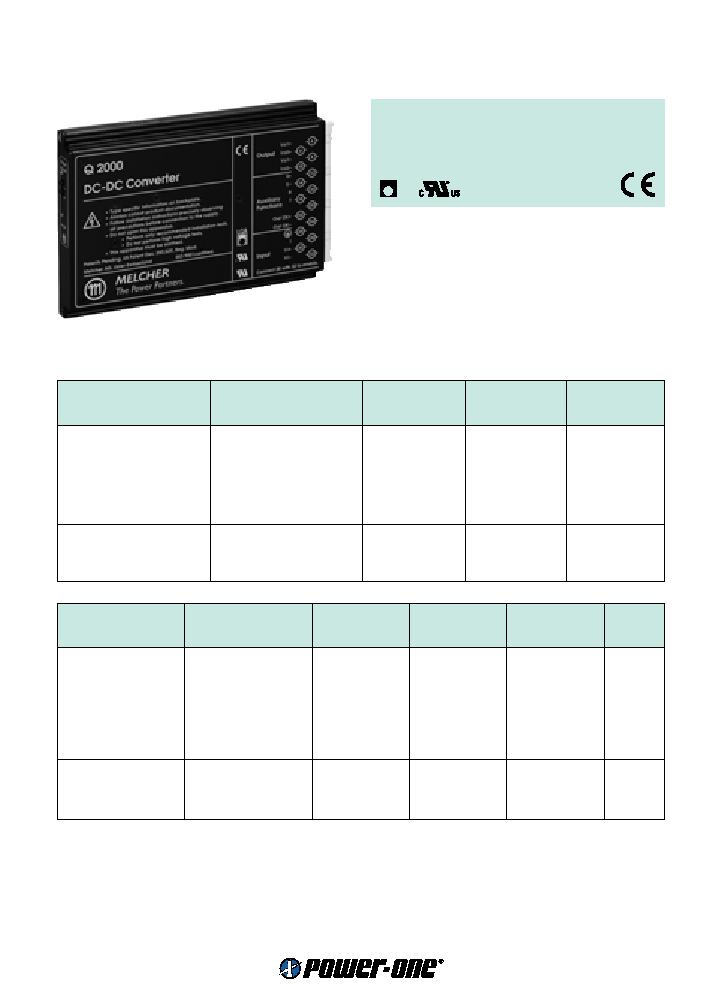
Cassette Style
Q Series
Input
Input voltage
refer to selection chart
Inrush current
ETS 300 132-2
typ. 40 A
Output
Efficiency
U
i nom
,
I
o nom
up to 88 %
Output voltage setting accuracy
U
i nom
,
I
o nom
±
0.6 %
U
o nom
Worst case output voltage 1
U
i min
...
U
i max
, 0...
I
o1 max
,
T
C min
...
T
C max
±
1.8 %
U
o nom
Minimum output current 1, 2
in parallel configuration not required
0 A
Minimum output current 1, 2
in individual or series configuration
10%
I
o1,2 nom
Load regulation output 2
I
o1,2 min
...
I
o1,2 max
typ. 100 m
∑ (
I
o1
≠
I
o2
)
Output voltage switching noise
IEC/EN 61204, total, peak-peak
typ 0.3%
U
o nom
Common current limit.
I
o1
+
I
o2
rectangular U/I characteristic
typ. 130% (
I
o1 max
+
I
o2 max
)
Operation of units in parallel
by connecting the current sharing pins T
Protection
Input reverse polarity
built-in fuse
Input undervoltage lockout
typ. 90 %
U
i min
Input overvoltage lockout
typ. 110 %
U
i max
Input transient protection
varistor
Output
no-load, overload and short-circuit proof
Output overvoltage
second control loop
typ. 125%
U
o nom
Overtemperature
switch-off with auto restart (-7 units)
T
C
typ. 100
∞
C
Control
Output voltage adjustment
with feature R
60/80...110%
U
o nom
Inhibit on input side
TTL input, output(s) disabled if left open circuit
Status indication
LEDs: In OK (-7 units), Out OK (all)
Output good signal (Out OK)
isolated open collector signal

3
www.power-one.com
Safety
Approvals
EN 60950, UL 1950, CSA C22.2 No. 950
Class of equipment
class I
Protection degree
IP 20/30
Electric strength test voltage
I/case, O/case, Out OK/case
1.5 kV AC
I/O, Out OK/I, Out OK/O
3 kV AC
O/O
300 V DC
EMC
Electrostatic discharge
IEC/EN 61000-4-2, level 4 (8/15 kV)
criterion B
Electromagnetic field
IEC/EN 61000-4-3, level 3 (10 V/m)
criterion A
Electr. fast transients/bursts
IEC/EN 61000-4-4, output/input, level 3/4 (2/4 kV)
criterion B
Surge
IEC/EN 61000-4-5, input, level 2/3 (1/2 kV)
criterion B
Conducted disturbances
IEC/EN 61000-4-6, level 2/3 (3/10 V)
criterion A
Electromagnetic emissions
CISPR 22/EN 55022, 24/48/BQ/CQ/GQ, conducted
class B
Environmental ≠2 units
Operating ambient temperature
U
i nom
,
I
o nom
, convection cooled
≠10...50
∞
C
Operating case temperature
T
C
U
i nom
,
I
o nom
≠10...80
∞
C
Storage temperature
non operational
≠25...100
∞
C
Damp heat
IEC/EN 60068-2-3, 93 %, 40
∞
C
21 days
Vibration, sinusoidal
IEC/EN 60068-2-6, 10...60/60...2000 Hz
0.15 mm/2 g
n
Shock
IEC/EN 60068-2-27, 6 ms
15 g
n
Bump
IEC/EN 60068-2-29, 6 ms
10 g
n
MTBF
MIL-HDBK-217F, G
B
, 40
∞
C, 24/48Q1000
588'000 h
Environmental ≠7 units
Operating ambient temperature
U
i nom
,
I
o nom
, convection cooled
≠25...71
∞
C
U
i nom
,
I
o max
, convection cooled
≠25...50
∞
C
Operating case temperature
T
C
U
i nom
,
I
o nom
≠25...95
∞
C
U
i nom
,
I
o max
≠25...85
∞
C
Storage temperature
non operational
≠40...100
∞
C
Damp heat
IEC/EN 60068-2-3, 93 %, 40
∞
C
56 days
Vibration, sinusoidal
IEC/EN 60068-2-6, 10...60/60...2000 Hz
0.35 mm/5 g
n
Shock
IEC/EN 60068-2-27, 11 ms
50 g
n
Bump
IEC/EN 60068-2-29, 11 ms
25 g
n
Random vibration
IEC/EN 60068-2-64, 20...500 Hz
4.9 g
n rms
MTBF
MIL-HDBK-217F, notice 2, G
B
, 40
∞
C, BQ 2000
853'000 h
Options
Extended temperature range
≠40...71
∞
C, ambient, operating, for -7 units
-9
Output voltage adjustment
±
10%
U
o nom
, excludes feature R and vice versa
P
Accessories
Front panels for 19" rack mounting in 3U or 6U configuration (Schroff/Intermas)
Mating H15 connectors with screw, solder, fast-on or press-fit terminals
Connector retention facilities and code key system for connector coding
Additional external input or output filters
Mechanical mounting supports for chassis, DIN-rail and PCB mounting
Q Series
60...132 Watt DC-DC Converters
4
www.power-one.com
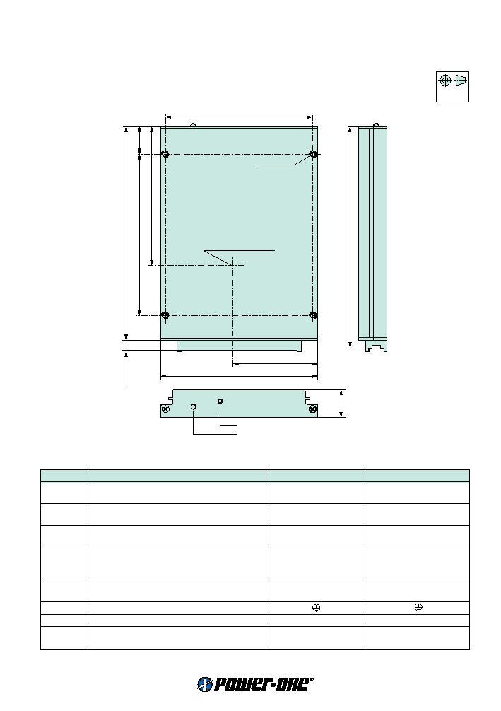
Mechanical data
Tolerances
±
0.3 mm (0.012") unless otherwise indicated.
European
Projection
Cassette Style
Q Series
104 (4.09")
60 (2.36")
111 (4.37")
20 (0.79")
105 (4.13")
127 (5.18")
164 (6.46")
8 (0.31")
19.8
(0.78")
Potentiometer (option P)
LED "OUT OK"
171.93 (DIN 41494) (6.76")
S09051
M3; 4 deep
Measuring point of
case temperature
T
C
Pin allocation
Pin
Electrical determination
Q 1000
Q 2000
4
Output voltage (positive)
Vo1+
Vo1+
6
Output voltage (positive)
Vo1+
Vo2+
8
Output voltage (negative)
Vo1≠
Vo1≠
10
Output voltage (negative)
Vo1≠
Vo2≠
12
Sense line (positive)
S+
S+
14
Sense line (negative)
S≠
S≠
16
Output voltage control input
R
R
18
Current sharing control input
T
T
20
Do not connect (internal Gnd.)
-
-
22
Output good signal (positive)
Out OK+
Out OK +
24
Output good signal (negative)
Out OK≠
Out OK ≠
26
Protective earth
28
Inhibit control input
i
i
30
Input voltage (positive)
Vi+
Vi +
32
Input voltage (negative)
Vi≠
Vi ≠