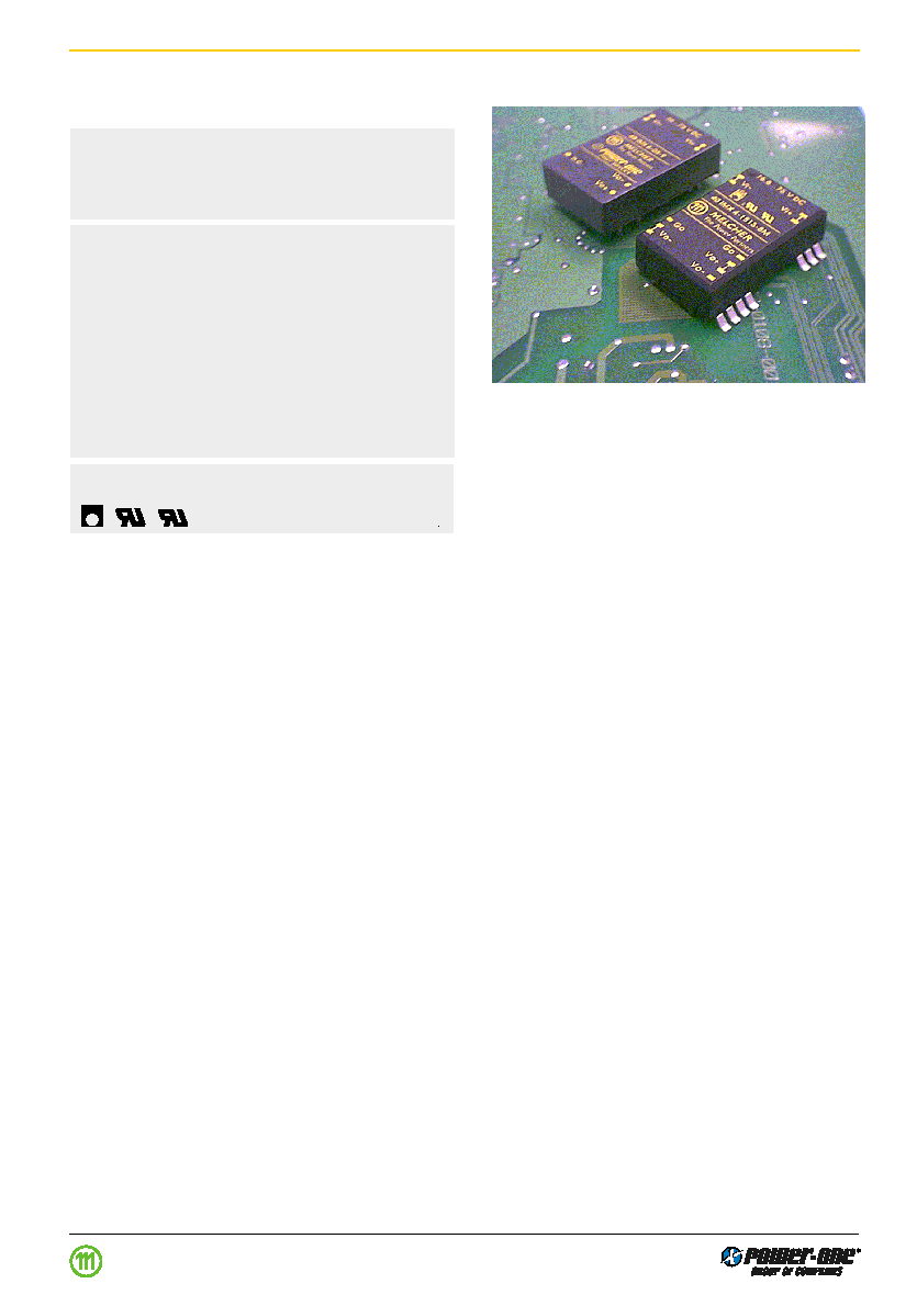
6 Watt SMD and through hole
IMS 6 Series
Input to output electric strength test up to 2 kV DC
Input voltage ranges:
18...36 and 36...75 V DC
Single and dual outputs of 5, 12, 15 V DC
∑ Wide input voltage ranges
∑ Electrical isolation, single and dual outputs
∑ Immunity to IEC/EN 61000-4-2, -3, -4, -5 and -6
∑ High efficiency (typ. 82%)
∑ Flex power: flexible load distribution
∑ No load and short-circuit proof
∑ High reliability and no derating
∑ Operating ambient temperature ≠40...+ 71 C
∑ Industrial, alternative and SMD pinout
∑ DIL 24 case with 9.0 mm profile
Safety approvals pending to IEC/EN 60950, UL 1950
LGA
C
Summary
The IMS 6 series of board mountable 6 W DC-DC convert-
ers has been designed according to the latest industry re-
quirements and standards. The converters are particularly
suitable for use in mobile or stationary applications in trans-
port, industry or telecommunications where variable input
voltages or high transient voltages are prevalent.
Covering a total input voltage range from 18 V DC up to
75 V DC.
The converters are designed and built according to the
international safety standards IEC/EN 60950, UL 1950,
CAN/CSA C22.2 No.950-95 and are LGA and UL marked.
A special feature is their small case size, DIL 24 with only
9.0 mm profile. The circuit comprises integrated planar
magnetics and all components are automatically assem-
bled and solidly soldered onto a single PCB without any
wire connections. Thanks to the rigid mechanical design the
units withstand an extremely high level of shock and vibra-
tions. Careful considerations of possible thermal stresses
ensure the absence of hot spots providing long life in envi-
ronments where temperature cycles are a reality. The ther-
mal design allows operation at full load up to an ambient
temperature of 71 C in free air without using any potting
material.
Options : SMD pinout or K-pinout, an alternative to the
standard industrial pinout, provide a high level of applica-
tion specific engineering and design-in flexibility.
Table of Contents
Page
Summary .......................................................................... 1
Type Survey and Key Data .............................................. 2
Type Key .......................................................................... 2
Functional Description ...................................................... 3
Electrical Input Data ......................................................... 4
Electrical Output Data ...................................................... 6
Page
Electromagnetic Compatibility (EMC) .............................. 8
Mechanical Data .............................................................. 9
Immunity to Environmental Conditions ........................... 10
Safety and Installation Instructions ................................ 11
Description of Options .................................................... 13
Edition 1 06.00
Industrial Environment DC/DC Converters < 40W IMS6 Series
o
DC/DC converters
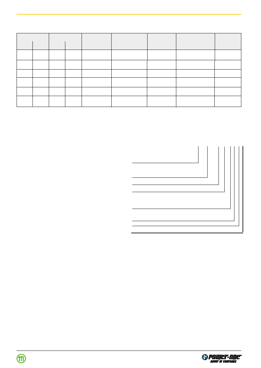
Type Survey and Key Data
Table 1: Type survey
Output 1
Output 2
Output Power
Input voltage
Efficiency
Type
Options
U
o1 nom
I
o1 nom
U
o2 nom
I
o2 nom
P
o nom
range
typ
designation
[V DC]
[A]
1
[V DC]
[A]
1
[W]
[V DC]
[%]
5
1000
-
-
5.0
18...36
82
24IMS6-05-9
M, K
, Z
1
Flexible load distribution on double outputs possible to 75% , 25% asymetric loading.
Type Key
48 IMS 6 - 05 05 -9 K M
Z
Input voltage range
U
i
16...36 V DC ............................................. 24
36...75 V DC
........................................... 48
Series ........................................................................ IMS 6
Output voltage type for output 1 ....................
..... 05, 12, 15
Output voltage type for output 2 .........................
05, 12, 15
Operating ambient temperature range
T
A
≠40...71 C .................................................. -9
Options:
Alternative pinout ......................................... K
1 2
SMD-pinout ................................................. M
1 2
1
Option M excludes option K and vice versa
2
For delivery lead times contact factory. Some types require a minimum order quantity.
Industrial Environment DC/DC Converters < 40W IMS6 Series
5
1000
-
-
5.0
36...75
82
48IMS6-05-9
M, K, Z
12
500
-
-
6.0
18...36
83
24IMS6-12-9
M, K, Z
12
500
-
-
6.0
36...75
83
48IMS6-12-9
M, K, Z
15
400
-
-
6.0
18...36
84
24IMS6-15-9
M, K, Z
15
400
-
-
6.0
36...75
84
48IMS6-15-9
M, K, Z
5
500
5
500
6.0
18...36
82
24IMS6-0505-9
M, K, Z
5
500
5
500
6.0
36...75
82
48IMS6-0505-9
M, K, Z
12
250
12
250
6.0
18...36
83
24IMS6-1212-9
M, K, Z
12
250
12
250
6.0
36...75
83
48IMS6-1212-9
M, K, Z
15
200
15
200
6.0
18...36
84
24IMS6-1515-9
M, K, Z
15
200
15
200
6.0
36...75
84
48IMS6-1515-9
M, K, Z
Edition 1 06.00
Open frame ................................................. Z
1 2
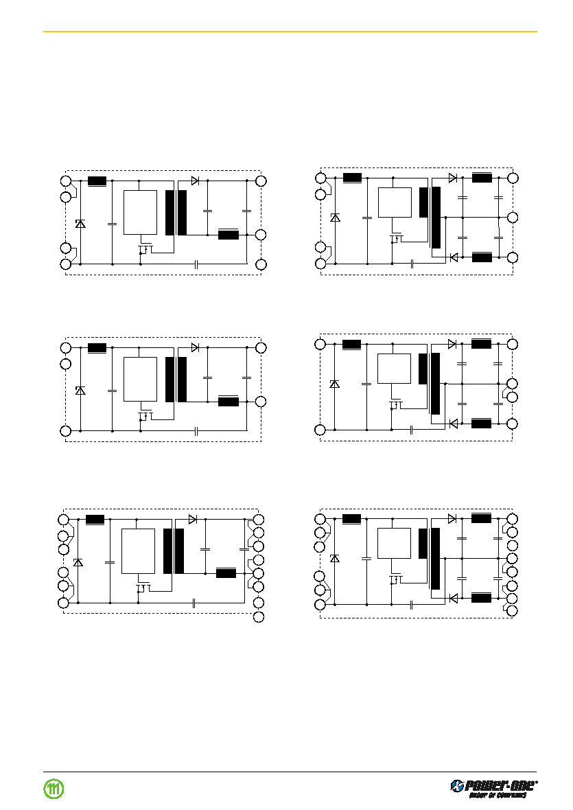
Functional Description
The IMS 6 DC-DC modules are feedback controlled flyback
converters using current mode PWM (Pulse Width Modula-
tion).
The converter input is protected against transients by
means of a suppressor diode.
The output voltage is monitored by a separate transformer
winding close to the secondary windings and fed back to
the control circuit.
Fig. 2
Block diagram for dual output types.
Standard industrial pinout.
Fig. 1
Block diagram for single output types.
Standard industrial pinout.
PWM
Vi+
Vi≠
Vo+
Vo≠
22
3
14
16
10
23
2
03044
PWM
Vi+
Vi≠
Vo+
Vo≠
Go
23
22
2
3
14
16
11
03045
PWM
Vi+
Vi≠
Vo+
Vo≠
1
24
13
12
2
03046
n.c.
PWM
Vi+
Vi≠
Vo+
Vo≠
Go
1
24
15
10
13
03047
11
Fig. 4
Block diagram for dual output types.
Special pinout (Option K).
Fig. 3
Block diagram for single output types.
Special pinout (Option K).
PWM
Vi+
Vi≠
Vo≠
22
2
13
12
03048
23
3
n.c.
10
Vo+
14
15
11
16
PWM
Vi+
Vi≠
Vo+
Vo≠
Go
22
2
14
10
12
03049
16
15
13
11
23
3
Fig. 6
Block diagram for dual output types.
SMD pinout (Option M).
Fig. 5
Block diagram for single output types.
SMD pinout (Option M).
Current limitation is provided by the primary circuit, thus
limiting the total output current (
I
o nom
for the single and
I
o1 nom
+
I
o2 nom
for the dual output types).
The close magnetic coupling provided by the planar con-
struction ensures very good regulation and allows for flex-
ible load distribution on dual output types.
Industrial Environment DC/DC Converters < 40W IMS6 Series
Edition 1 06.00
24
1
9
n.c.
9
1
24
n.c.

Electrical Input Data
General conditions:
T
A
= 25 C, unless
T
C
is specified.
Table 2: Input Data
Input
24 IMS 6
48 IMS 6
Characteristics
Conditions
min
typ
max min
typ
max
Unit
U
i
Input voltage range
T
C min
...
T
C max
18
36
36
75
V DC
U
i nom
Nominal input voltage
I
o
= 0...
I
o nom
U
i sur
Repetitive surge voltage
abs. max input (3 s)
40
100
t
start up
Converter start-up time
1
Worst case condition at
0.25
0.5
0.25
0.5
s
U
i min
and full load
t
rise
Rise time
1
U
i nom
resistive load
5
5
ms
I
o nom
capacitive load
12
12
I
i o
No load input current
I
o
= 0,
U
i min
...
U
i max
15
20
mA
C
i
Input capacitance
for surge calculation
0.54
0.3
uF
I
inr p
Inrush peak current
U
i
=
U
i nom
3
3.7
4.2
A
f
s
Switching frequency
U
i min
...
U
i max
,
I
o
= 0...
I
o nom
approx. 400
approx. 400
kHz
I
i rr
Reflected ripple current
I
o
= 0...
I
o nom
30
30
mA
pp
u
i RFI
Input RFI level
EN 55022
2
B
1
conducted and radiated
1
Measured with a resistive or max. admissible capacitive load. (See fig.:
Converter start-up and rise time)
2
External filter required. (See:
Filter recommendations for compliance with EN 55022)
3
Source impedance according to prETS 300132-2, version 4.3.
Industrial Environment DC/DC Converters < 40W IMS6 Series
48
24
5
10
B
1
Edition 1 06.00
Industrial Environment DC/DC Converters < 40W IMS6 Series
Edition 1 06.00
U
o nom
U
o
t
start up
t
rise
t
04008
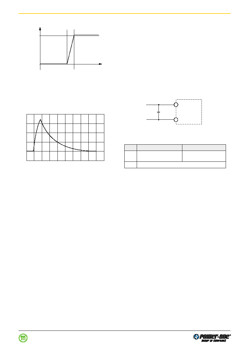
Fig. 7
Converter start-up and rise time
1 A/Div.
5 s/Div.
04034
0
1
2
3
4
Inrush Current
The inrush current has been kept as low as possible by
choosing a very small input capacitance. A series resistor
may be inserted in the input line to limit this current further.
Fig. 8
Typical inrush current at U
i nom
, P
o nom
versus time
(48 IMS6 ) measured according to prETS 300132-2,
version 4.3.
Reverse Polarity Protection at Input
The suppressor diode on the input also provides for reverse
polarity protection by conducting current in the reverse di-
rection, thus protecting the unit. An external fuse is required
to limit this current:
≠ For 24 IMS 6 a fast 0.63 A (F0.63A) fuse is recommended
≠ For 48 IMS 6 a fast 0.35 A (F035A) fuse is recommended
Filter recommendations for compliance with EN 55022
Electromagnetic emission requirements according to table
Input data can be achieved by adding an external capacitor
as close as possible to the input terminals.
Fig. 9
Input filter arrangement
Vi+
Vi≠
C
i
04035
Table 3: Input filter components (EN 55022)
Ref.
24 IMS 6
48 IMS 6
C
1
,
2.2
F
,
100 V,
2.2 F
,
150 V,
Type
ceramic or film

Electrical Output Data
General conditions:
T
A
= 25 C, unless
T
C
is specified.
Table 6a: Output data for single output units
Output
U
o nom
5.0 V
12.0 V
15.0 V
Characteristics
Conditions
min typ max
min typ max
min typ max
Unit
U
o
Output voltage
U
i nom,
I
o
= 0.5
I
o nom
4.96
5.04
11.90
12.10
14.88
15.12
VDC
I
o nom
Output current
U
i min
...
U
i max
1000
500
400
mA
I
o L
Current limit
2
U
i nom
,
T
C
= 25 C
1400
700
600
U
o U
Line regulation
U
i min
...
U
i max
,
I
o nom
1
1
1
%
U
Load regulation
U
i nom
3
3
3
I
o
= (0.1...1)
I
o nom
u
o1, 2
Output voltage noise
U
i min
...
U
i max
5
80
120
150
mV
pp
I
o
=
I
o nom
6
20
40
40
60
50
75
U
o clp
Output overvoltage
Min. load 1%
130
130
130
%
limitation
C
o ext
Admissible
680
150
100
uF
capacitive load
3
u
o d
Dynamic Voltage deviat.
U
i nom
250
250
250
mV
t
d
load
Recovery time
I
o nom
1
/
2
I
o nom
1
1
ms
regulat.
Uo
Temperature coefficient
U
i min
...
U
i max
0.02
0.02
0.02
%/K
U
o
/
T
C
I
o
= 0...
I
o nom
Table 6b: Output data for dual output units
Output
U
o nom
5 V
12 V
15 V
Characteristics
Conditions
min typ max
min typ max
min typ max
Unit
U
o1
Output voltage
U
i nom
4.96
5.04
11.90
12.10
14.88
15.12
VDC
U
o2
I
o1
=
I
o2
= 0.5
I
o nom
4.95
5.05
11.88
12.12
14.85
15.15
I
o nom
Output current
1
U
i min
...
U
i max
2
500
2
350
2
200
mA
U
o U
Line regulation
U
i min
...
U
i max
,
I
o nom
1
1
1
U
Load regulation
4
U
i nom
3
3.5
3
I
o
= (0.1...1)
I
o nom
u
o1, 2
Output voltage noise
U
i min
...
U
i max
5
100
140
150
mV
pp
I
o
=
I
o nom
6
40
60
45
70
50
75
U
o clp
Output overvoltage
Min. load 1%
130
130
130
%
limitation
C
o ext
Admissible
680
150
100
uF
capacitive load
3
u
o d
Dynamic Voltage deviat.
U
i nom
250
600
750
mV
t
d
load
Recovery time
I
o nom
1
/
2
I
o nom
1
1
1
ms
regulat.
Uo
Temperature coefficient
U
i min
...
U
i max
0.02
0.02
0.02
%/K
U
o
/
T
C
I
o
= 0...
I
o nom
1
Each output capable of delivering full output power.
2
The current limit is primary side controlled.
3
Sum of both outputs.
4
Conditions for specified output. Other output loaded with constant current
I
o
= 0.5
I
o nom
.
5
BW = 20 MHz
6
Measured with a probe according to EN 61204.
Industrial Environment DC/DC Converters < 40W IMS6 Series
Edition 1 06.00
N/A
%
N/A
x
x
x
Output overvoltage protection
The outputs of the IMS 6 converters are protected against
overvoltages by Zener diodes. In the event of an overvolt-
age on the output, the unit will shut-down and attempt to
restart automatically. The main purpose of this feature is to
protect against possible overvoltages which could occur
due to a failure in the feedback control circuit. The units are
not designed to withstand external overvoltages applied to
the outputs.
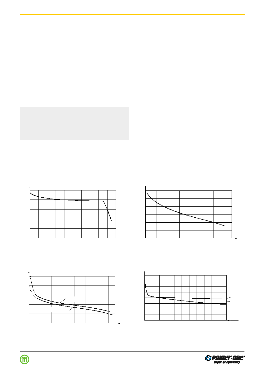
Connection in series
The outputs of single or dual output units can be connected
in series without any precautions, taking into consideration
that the highest output voltage should remain below 60 V for
SELV operation.
Connection in parallel
The outputs of several units with equal nominal output volt-
age can be connected in parallel. Approximate current
sharing between 2 or several units is ensured by their load
dependent output characteristic.
Fig. 12
U
o
versus I
o
(typ) of single output units (example for
48IMS6-05-9
Fig. 13
U
o
versus I
o
(typ) of dual output units ( 15 V), with 30 V
load connected to Vo+ and Vo≠.
5.25
5.0
4.75
4.5
4.25
4.0
0
I
o
[A]
U
o
[V]
05056
28.5
29
29.5
30
30.5
31
31.5
U
o1
+ U
o2
[V]
33
66
100
133
166
200
233
I
o
[mA]
0
05057
14
14.5
15
15.5
16
16.5
U
o1
[V]
33
66
100
33
66
200
233
I
o1
[mA]
0
I
o2
= 140 mA
I
o2
= 14 mA
05058
U
o1
, U
o2
[V]
I
o1
I
o1 no
05059
12.8
12.4
12
11.6
11.2
0
150
300
[%]
U
o2
U
o1
Thermal Considerations
If a converter, mounted on a PCB, is located in free, quasi-
stationary air (convection cooling) at the indicated maxi-
mum ambient temperature
T
A max
(see table:
Temperature
specifications) and is operated at its nominal input voltage
and output power, the case temperature
T
C
measured at
the:
Measuring point of case temperature T
C
(see: Me-
chanical Data) will approach the indicated value T
C max
af-
ter the warm-up phase. However, the relationship between
T
A
and
T
C
depends heavily on the conditions of operation
and integration into a system. The thermal conditions are
influenced by input voltage, output current, airflow, tem-
perature of surrounding components and surfaces and the
properties of the printed circuit board.
T
A max
is therefore
only an indicative value and under practical operating con-
ditions, the ambient temperature
T
A
may be higher or lower
than this value.
Caution: The case temperature
T
C
measured at the
Measuring point of case temperature T
C
(see: Mechani-
cal Data) may under no circumstances exceed the speci-
fied maximum value. The installer must ensure that un-
der all operating conditions
T
C
remains within the limits
stated in the table
Temperature specifications.
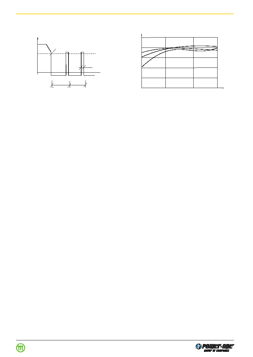
Short Circuit Behaviour
The current limit characteristic shuts down the converter
whenever a short circuit is applied to its output. It acts self-
protecting and automatically recovers after removal of the
overload condition.
Typical Performance Curves
Fig. 14
Cross load regulation of dual output units. U
o1
versus
I
o1
(typ) for various I
o2
(48IMS6-1515-9).
Fig. 15
Flexible load distribution on dual outputs (2 x 12 V) with
load variation from 0...150% of P
o1 nom
on output 1.
Output 2 loaded with 25% of P
o2 nom
.
Industrial Environment DC/DC Converters < 40W IMS6 Series
Edition 1 06.00
1.0
0.5
70
100
U
o
[%]
t [ms]
05041
8.5
60.5
60.5
overload short circuit condition
switch-off
40
50
60
70
80
90 [%]
05060
25
50
75
100
P
o nom
[%]
U
i nom
U
i max
U
i min
Fig. 16
Overload switch-off (hiccup mode).
Frequency of pulses: 16.5 Hz, puls duration: 8.5 ms.
Fig. 17
Efficiency versus input voltage and load.
Typical values (48IMS6 -1212-9)
Industrial Environment DC/DC Converters < 40W IMS6 Series
Edition 1 06.00
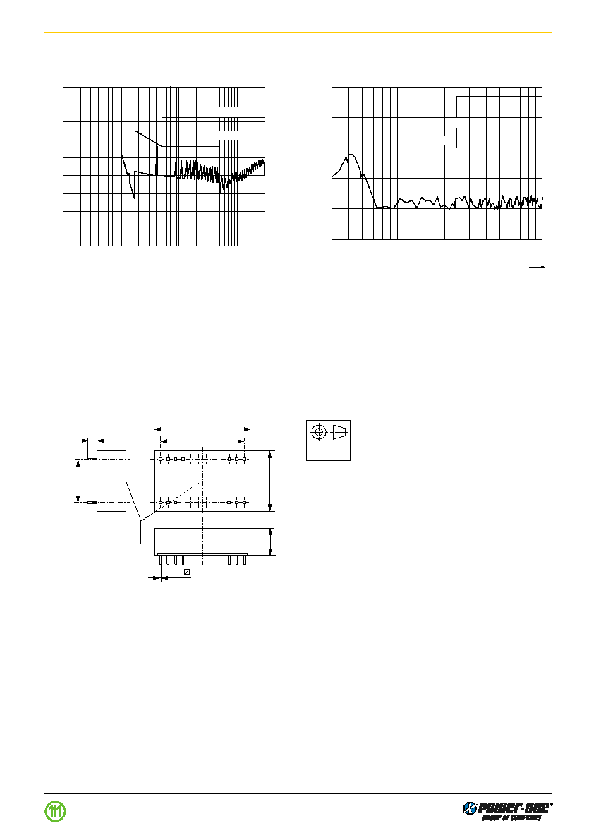
Fig. 18
Typical disturbance voltage (quasi-peak) at the input ac-
cording to CISPR 11/EN 55011 and CISPR 22/EN 55022,
measured at U
i nom
and I
o nom
. Output leads 0.1 m, twisted.
External capacitor at the input required (see: Recommen-
dations for compliance with EN 55022). (48 IMS6-1515-9)
Fig. 19
Typical radio frequency interference voltage at U
i nom
,
I
o nom
, measured with an antenna (distance 10 m). Output
leads 0.1 m, twisted (48 IMS6-1515-9).
07033
EN 55022 A
EN 55022 B
90
80
70
60
50
40
30
20
10
0
0
.01
0
.05
0.1
0.5
1
2
5
10
20
30
[dB V]
MHz
0
.02
EN 55022 B
50
40
30
20
10
0
30
50
100
200
500
1000
Frequency [MHz]
[dB V/m]
07034
Electromagnetic Emission
Conducted RFI noise at input according to EN 55022
Radiated RFI noise according to EN 55022.
Mechanical Data
Dimensions in mm. Tolerances 0.3 mm unless otherwise indicated.
European
Projection
Fig. 20
Case DIL 24, for IMS6
Weight: <10 g
15.24
33
1
min. 3
20
12
13
24
11 x 2.54 = 27.94
09042
Measuring point of
case temperature
T
C
0.5
8.5
Edition 1 06.00
Industrial Environment DC/DC Converters < 40W IMS6 Series
Immunity to Environmental Conditions
Table 8: Mechanical stress
Test Method
Standard
Test Conditions
Status
Ca
Damp heat
IEC/DIN IEC 60068-2-3
Temperature:
40
2
C
Unit not
steady state
MIL-STD-810D section 507.2
Relative humidity:
93
+2/-3
%
operating
Duration:
56 days
Ea
Shock
IEC/EN/DIN EN 60068-2-27
Acceleration amplitude:
100 g
n
= 981 m/s
2
Unit
(half-sinusoidal)
MIL-STD-810D section 516.3
Bump duration:
6 ms
operating
Number of bumps:
18 (3 each direction)
Eb
Bump
IEC/EN/DIN EN 60068-2-29
Acceleration amplitude:
40 g
n
= 392 m/s
2
Unit
(half-sinusoidal)
MIL-STD-810D section 516.3
Bump duration:
6 ms
operating
Number of bumps:
6000 (1000 each direction)
Fc
Vibration
IEC/EN/DIN EN 60068-2-6
Acceleration amplitude:
0.35 mm (10...60 Hz)
Unit
(sinusoidal)
MIL-STD-810D section 514.3
5 g
n
= 49 m/s
2
(60...2000 Hz)
operating
Frequency (1 Oct/min):
10...2000 Hz
Test duration:
7.5 h (2.5 h each axis)
Fda
Random vibration
IEC 60068-2-35
Acceleration spectral density: 0.05 g
n
2
/Hz
Unit
wide band
Frequency band:
10...500 Hz
operating
reproducibility
Acceleration magnitude:
4.9 g
n rms
high
Test duration:
3 h (1 h each axis)
Kb
Salt mist, cyclic
IEC/EN/DIN IEC 60068-2-52
Concentration:
5% (30 C)
Unit not
(sodium chloride
Duration:
2 h per cycle
operating
NaCl solution)
Storage:
40 C, 93% rel. humidity
Storage duration:
22 h per cycle
Number of cycles:
3
Table 9: Temperature specifications, valid for air pressure of 800...1200 hPa (800...1200 mbar)
Temperature
Standard -9
Characteristics
Conditions
min
max
Unit
T
A
Ambient temperature
1
Operational
2
≠40
71
C
T
C
Case temperature
≠40
100
T
S
Storage temperature
1
Non operational
≠40
100
1
MIL-STD-810D section 501.2 and 502.2
2
See
Thermal Considerations
Table 10: MTBF and device hours
MTBF
Ground Benign
Ground Fixed
Ground Mobile
Device Hours
1
MTBF acc. to MIL-HDBK-217F
T
C
= 40 C
T
C
= 40 C
T
C
= 70 C
T
C
= 50 C
48IMS6-05-9
2'651'000 h
349'000 h
124'000 h
119'000 h
1
Statistical values, based on an average of 4300 working hours per year and in general field use
Industrial Environment DC/DC Converters < 40W IMS6 Series
Edition 1 06.00
Safety and Installation Instructions
Installation Instruction
Installation of the DC-DC converters must strictly follow the
national safety regulations in compliance with the enclo-
sure, mounting, creepage, clearance, casualty, markings
and segregation requirements of the end-use application.
Connection to the system shall be made via a printed circuit
board according to:
Mechanical Data.
The units should be connected to a secondary circuit.
Check for hazardous voltages before altering any connec-
tions.
Do not open the module.
Ensure that a unit failure (e.g. by an internal short-circuit)
does not result in a hazardous condition. See also:
Safety
of operator accessible output circuit.
Table 11: Pin allocation for standard industrial pinout
Pin
Single output units
Dual output units
2
Vi≠
Vi≠
3
Vi≠
Vi≠
10
n.c.
-
11
-
Vo≠
14
Vo+
Vo+
16
Vo≠
Go
22
Vi+
Vi+
23
Vi+
Vi+
Table 12: Pin allocation for K pinout (option K)
Pin
Single output units
Dual output units
1
Vi+
Vi+
2
n.c.
-
10
-
Go
11
-
Go
12
Vo≠
-
13
Vo+
Vo≠
15
-
Vo+
24
Vi≠
Vi≠
Table 13: Pin allocation for SMD pinout (option M)
Pin
Single output units
Dual output units
2
V i≠
Vi≠
3
V i≠
Vi≠
10
n.c.
Go
11
Vo≠
Vo≠
12
Vo≠
Vo≠
13
Vo+
Vo≠
14
Vo+
Vo+
15
Vo+
Vo+
16
Vo≠
Go
22
Vi+
Vi+
23
Vi+
Vi+
1
12
13
24
10013
Bottom view
Fig. 22
Pin numbering
Input Fuse
To prevent excessive current flowing through the input sup-
ply line in case of a short-circuit across the converter input
an external fuse should be installed in a non earthed input
supply line. We recommend a fast acting fuse F0.5A
for 24 IMS 6 and F0.315A for 48 IMS 6 types.
Standards and approvals
All DC-DC converters are UL recognized according to UL
1950, UL recognized for Canada to CAN/CSA C22.2 No.
950-95 and LGA approved to IEC/EN 60950 standards.
The units have been evaluated for:
∑ Building in
∑ Supplementary insulation input to output, based on their
maximum input voltage
∑ The use in a pollution degree 2 environment
∑ Connecting the input to a secondary circuit which is sub-
ject to a maximum transient rating of 1500 V.
The DC-DC converters are subject to manufacturing sur-
veillance in accordance with the above mentioned UL,
CSA, EN and ISO 9001 standards.
Safety of operator accessible output circuits
If the output circuit of a DC-DC converter is operator acces-
sible, it shall be an SELV circuit according to IEC/EN 60950
related safety standards
The insulation concept table below shows some possible
installation configurations, compliance with which causes
the output circuit of the DC-DC converter to be an SELV cir-
cuit according to IEC/EN 60950 up to a configured output
voltage (sum of nominal voltages if in series or +/≠ configu-
ration) of 46 V.
However, it is the sole responsibility of the installer to en-
sure the compliance with the relevant and applicable safety
regulations. More information is given in:
Technical Infor-
mation: Safety.
Industrial Environment DC/DC Converters < 40W IMS6 Series
Edition 1 06.00
24
Vi-
Vi+
9
n.c.
n.c.
1
Vi+
Vi+

Table 14: Electric strength test voltages
Characteristic
Input - Output
Unit
24/48 IMS 6
Electric strength
1.2
kV
rms
test voltage 1 s
1.5
kV DC
Coupling
1.2
nF
capacitance
Insulation resist.
>100
M
at 500 V DC
Partial discharge
Consult factory
kV
extinction voltage
AC-DC
front
end
DC-DC
con-
verter
Mains
Fuse
Battery
Earth
connection
Suppressor
diode
SELV
Earth
connection
+
≠
~
~
10004
Fig. 23
Schematic safety concept. Use fuse, suppressor diode
and earth connection as per table: Safety concept leading
to an SELV output circuit
.
Table 15: Insulation concept leading to an SELV output circuit
Conditions Front end
DC-DC converter
Result
Supply
Minimum required grade
Maximum
Minimum required safety
Measures to achieve the
Safety status of
voltage
of isolation, to be provided DC output
status of the front end
specified safety status of the
the DC-DC
by the AC-DC front end,
voltage
output circuit
output circuit
converter output
including mains supplied
from the
circuit
battery charger
front end
1
Mains
Basic
60 V
Earthed SELV circuit
2
Operational insulation, pro-
SELV circuit
250 V AC
vided by the DC-DC converter
ELV circuit
Input fuse
3
output suppressor
Earthed SELV
>60 V
Hazardous voltage
diodes
4
, and earthed
circuit
secondary circuit
output circuit
2
Double or reinforced
60 V
SELV circuit
Operational insulation, pro-
SELV circuit
vided by the DC-DC converter
1
The front end output voltage should match the specified input voltage range of the DC-DC converter.
2
The earth connection has to be provided by the installer according to the relevant safety standard, e.g. IEC/EN 60950.
3
The installer shall provide an approved fuse (type with the lowest rating suitable for the application) in a non-earthed input line directly
at the input of the DC-DC converter (see fig.:
Schematic safety concept). For UL's purpose, the fuse needs to be UL-listed. See also:
Input Fuse.
4
Each suppressor diode should be dimensioned in such a way, that in the case of an insulation fault the diode is able to limit the output
voltage to SELV (<60 V) until the input fuse blows (see fig.:
Schematic safety concept).
5
Has to be insulated from earth by double or reinforced insulation according to the relevant safety standard, based on the maximum
output voltage from the front end.
Cleaning Agents
In order to avoid possible damage, any penetration of
cleaning fluids has to be prevented, since the power sup-
plies are not hermetically sealed.
Protection Degree
The protection degree of the DC-DC converters is IP 30.
Isolation
The electric strength test is performed as factory test in ac-
cordance with IEC/EN 60950 and UL 1950 and should not
be repeated in the field. Melcher will not honour any guar-
antee claims resulting from electric strength field tests.
Edition 1 06.00
Industrial Environment DC/DC Converters < 40W IMS6 Series
Option M
Surface mount version.
Note: Precautions should be taken when reflow soldering
the SMD version, option M. The reflow soldering instruc-
tions below should be strictly adhered to. An inadequate
soldering process may permanently damage the converter
or degrade its performance and Melcher will not honour any
guarantee/warranty claims resulting from damage caused
by ignoring the soldering instructions.
Infrared soldering is not permitted.
The surface mountable version of this product is assem-
bled with high melting point solder (227 C) to ensure that
the solder joints of of the internal components do not de-
grade in the end users SMD soldering process.
This product is only specified for "Forced Convection
Reflow Soldering" (Hot Air). Any conventional soldering
profile is acceptable provided that the restriction curve be-
low is not exceeded at any time during the reflow process.
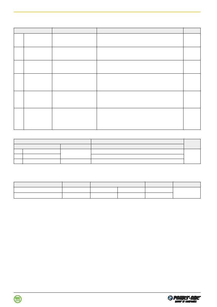
Description of Options
Table 16: Survey of options
Option
Function of option
Characteristic
Z
Available in 'open frame' version without case
M
Surface mount version, SMD
Not available for 5 IMX 4 and 70 IMX 4 types
K
Alternative pinout
Not available for 5 IMX 4 and 70 IMX 4 types as well as all types
with 3.3 V or 24 V outputs
210
220
230
240
0
10
20
30
T
peak
[ C]
11051
40
t [s]
50
205
215
225
235
Option K
Alternative pinout.
This option defines an alternative pinout.
Option K excludes option M and vice versa.
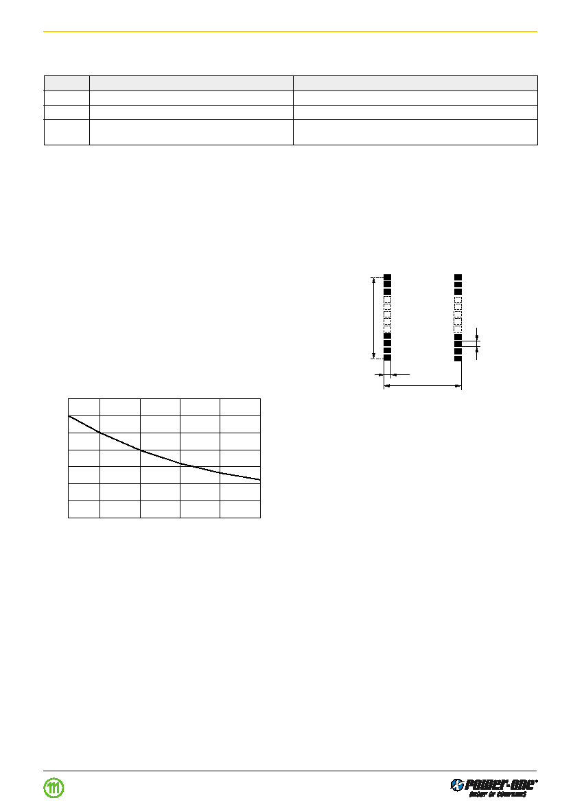
Fig. 24
Forced convection reflow soldering restriction curve
measured on pin 2
26.6
2.5
2
27.94 ( 1
1
x 2.54)
1
12
24
13
11
0
5
2
26.6
2.5
2
27.94 ( 1
1
x 2.54)
1
12
24
13
11
0
5
2
Fig. 25
Proposed solder lands.
Edition 1 06.00
Industrial Environment DC/DC Converters < 40W IMS6 Series
Bare board construction without case. Consult factory.