1
FEATURES
∑ Remote ON/OFF and TRIM
∑ Overcurrent Protection and Thermal Shutdown
∑ Efficiencies to 83%
∑ 700V Isolation, Up to 1544V on 48V Converters
∑ Power Density up to 11 Watts per Cubic Inch
∑ Five-Side Shielded Case
∑ Extended Range Input (2:1)
DFA20 SERIES
SINGLE OUTPUT
1
BOTTOM VIEW
SIDE VIEW
0.000
0.000
0.25
0.000
2.02
(51.31)
(6.35)
0.040 (1.02) DIA
6 PLACES
0.45
2.02
(11.43)
(51.31)
2
3
7
6
5
1.800
0.11
0.700
0.300
0.100
0.600
0.400
0.51
(7.62)
(2.54)
(13.0)
(17.78)
(15.24)
(10.16)
(45.72)
(2.8)
NOTES
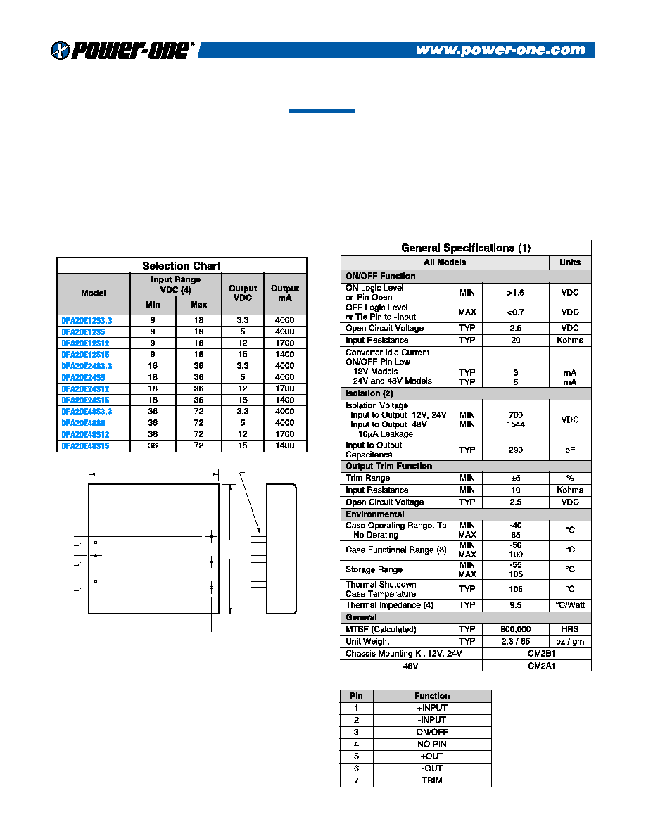
(1)
All parameters measured at Tc = 25∞C, nominal input voltage and full rated load unless otherwise noted.
Refer to the Technical Reference Section for the definition of terms, measurement circuits and other
information.
(2)
The Case is tied to the -Input, Pin 2.
(3)
The functional temperature range is intended to give an additional data point for use in evaluating this
power supply. At the low functional temperature the power supply will function with no side effects,
however, sustained operation at the high functional temperature will reduce expected operational life.
The data sheet specifications are not guaranteed beyond the case operating range.
(4)
The case thermal impedance is specified as the case temperature rise over ambient per package watt
dissipated.
Mechanical tolerances unless otherwise noted:
X.XX dimensions: ±0.020 inches
X.XXX dimensions: ±0.005 inches
DESCRIPTION
The compact DFA20 Series provides power densities up to 11 watts
per cubic inch (0.67 watts per cm
3
). Ideal for battery operated
industrial, medical control and remote data collection systems, this
converter has fully filtered inputs and outputs. Complete overload
protection with independent pulse-by-pulse current limiting and an
overtemperature shutdown ensures reliable system operation. The
output of the converter is electrically isolated, thereby allowing the
output to be configured as a positive or negative output voltage.
Rev. 04/2000
2
DFA20 SERIES ≠ SINGLE OUTPUT
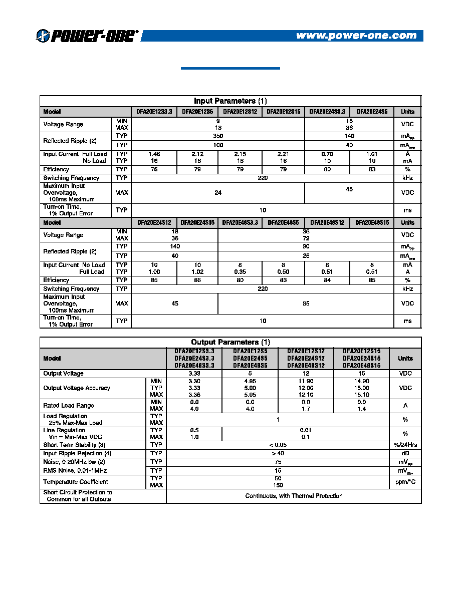
NOTES
(1)
All parameters measured at Tc=25∞C, nominal input voltage and full rated load unless otherwise
noted. Refer to the Technical Reference Section for the definition of terms, measurement circuits and
other information.
(2)
Noise is measured per Technical Reference Section. Measurement bandwidth is 0-20 MHz for peak-
peak measurements, 10 kHz to 1 MHz for RMS measurements. Output noise is measured with a
0.01µF ceramic in parallel with a 1µF/35V Tantalum capacitor located 1" away from the converter to
simulate your PCB's standard decoupling. Input reflected ripple is measured into a 10µH source
impedance.
(3)
Short term stability is specified after a 30 minute warmup at full load, constant line and recording
the drift over a 24 hour period.
(4)
The input ripple rejection is specified for DC to 120 Hz ripple with a modulation amplitude of 1% of
Vin.

3
5
+OUT
7
TRIM
10K
LOAD
USING TRIMPOT
6
-OUT
5
+OUT
7
TRIM
TRIM
DOWN
TRIM
UP
LOAD
USING FIXED RESISTORS
6
-OUT
DFA20 SERIES ≠ SINGLE OUTPUT
DFA20 SERIES APPLICATION NOTES:
External Capacitance Requirements
No external capacitance is required for operation of the DFA20
Series. The use of input capacitors with less than 0.5 ESR may
cause peaking in the input filter and degrade filter performance.
External output capacitance is not required for operation, however
it is recommended that 1 F to 10 F of tantalum and 0.001 to
0.1 F ceramic capacitance be selected for reduced system noise.
Additional output capacitance may be added for increased
filtering, but should not exceed 400 F.
Negative Outputs
A negative output voltage may be obtained by connecting the
+OUT to circuit ground and connecting -OUT as the negative
output.
Remote ON/OFF Operation
The remote ON/OFF pin may be left floating if this function is not
used. It is recommended to drive this pin with an open collector
arrangement or a relay contact. When the ON/OFF pin is pulled
low with respect to the -INPUT, the converter is placed in a low
power drain state.
Output TRIM
The TRIM pin may be used to adjust the output ±5% from the
nominal setting. This function allows adjustment for voltage drops
in the system wiring, as well 5.2 volt outputs for ECL applications.
Figure 1 shows the proper connections to use this function. A
trimpot value of 10K should be used for 3.3 and 5 volt outputs.
A trimpot value of 20K should be used for 12 and 15 volt
outputs. If the TRIM function is not required the pin may be
left floating.
Figure 1.
DFA20 SERIES BLOCK DIAGRAM
5
+ OUTPUT
ISOLATION TRANSFORMER
+
6
7
TRIM
ISOLATED
FEEDBACK
LOW TC
BANDGAP
REFERENCE
FIVE SIDED SHIELDED COPPER CASE
+
≠
2
≠ INPUT
ON/OFF
1
3
+ INPUT
CURRENT
MODE
PWM
THERMAL SHUTDOWN
LC
INPUT
FILTER
- OUT
50
0
5
10
15
20
60
70
80
90
100
OUTPUT POWER DERATING
AMBIENT TEMPERATURE
POWER OUTPUT
NUCLEAR AND MEDICAL APPLICATIONS Power-One products are not authorized for use as critical components in life support systems, equipment used in hazardous environments,
or nuclear control systems without the express written consent of the President of Power-One, Inc.
TECHNICAL REVISIONS The appearance of products, including safety agency certifications pictured on labels, may change depending on the date manufactured. Specifications are
subject to change without notice.
4
DFA20 SERIES ≠ SINGLE OUTPUT
120
100
60
CURRENT LIMIT MODE >
80
40
20
0
0
80
20
40
100
120
140
60
OUTPUT VOLTAGE Vs. OUTPUT LOAD
OUTPUT LOAD (%)
NORMALIZED OUTPUT (%)
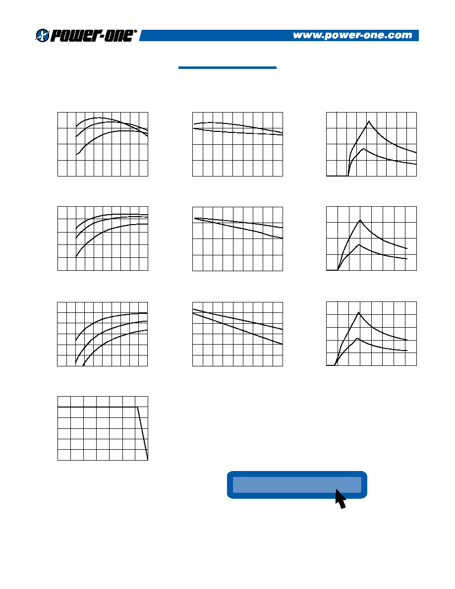
Typical Performance: (Tc=25∞C, Vin=Nom VDC, Rated Load)
80
85
75
70
65
60
90
0
40
30
20
LINE = 72VDC
LINE = 48VDC
LINE = 36VDC
10
50
60
70
80
90 100
48 VOLT EFFICIENCY Vs. LOAD
LOAD (%)
EFFICIENCY (%)
NOTES ON USING THE CURVES
1)
The input currents are for 20 watts of output power. For
±5 volt output models the current is approximately 15% less.
2)
The efficiency curves are for 12 volt output models. To use for other models adjust as follows:
±5 volt models subtract approximately 3%.
±15volt models add approximately 1%.
80
75
70
65
85
0
40
30
20
LINE = 18VDC
LINE = 12VDC
LINE = 9VDC
10
50
60
70
80
90 100
12 VOLT EFFICIENCY Vs. LOAD
LOAD (%)
EFFICIENCY (%)
85
80
75
70
65
9
15
16
17
14
13
12
100% FULL LOAD
50% FULL LOAD
10
11
18
12 VOLT EFFICIENCY Vs. LINE INPUT VOLTAGE
LINE INPUT (VOLTS)
EFFICIENCY (%)
80
85
75
70
65
90
0
40
30
20
LINE = 36VDC
LINE = 24VDC
LINE = 18VDC
10
50
60
70
80
90 100
24 VOLT EFFICIENCY Vs. LOAD
LOAD (%)
EFFICIENCY (%)
85
80
75
70
90
18
30
32
34
28
26
24
100% FULL LOAD
50% FULL LOAD
20
22
36
24 VOLT EFFICIENCY Vs. LINE INPUT VOLTAGE
LINE INPUT (VOLTS)
EFFICIENCY (%)
85
75
80
70
65
60
90
36
60
64
68
56
52
48
100% FULL LOAD
50% FULL LOAD
40
44
72
48 VOLT EFFICIENCY Vs. LINE INPUT VOLTAGE
LINE INPUT (VOLTS)
EFFICIENCY (%)
1.0
0.8
0.6
0.2
0.4
0.0
0
40
30
20
100% LOAD
50% LOAD
10
50
60
80
70
48 VOLT INPUT CURRENT Vs. LINE INPUT VOLTAGE
LINE INPUT (VOLTS)
INPUT CURRENT (AMPS)
2.0
1.5
1.0
0.5
0.0
0
20
15
10
100% LOAD
50% LOAD
5
25
30
40
35
24 VOLT INPUT CURRENT Vs. LINE INPUT VOLTAGE
LINE INPUT (VOLTS)
INPUT CURRENT (AMPS)
4
3
2
1
0
0
8
6
4
100% LOAD
50% LOAD
2
10
12
16
14
18
12 VOLT INPUT CURRENT Vs. LINE INPUT VOLTAGE
LINE INPUT (VOLTS)
INPUT CURRENT (AMPS)
www.power-one.com
www.power-one.com
For the Most Up-To-Date Information
24 Hours/Day--7 Days/Week