
DESCRIPTION
The DFC25 Series DC/DC converter provides tightly regulated
output voltages for industrial and datacom applications from 12, 24,
or 48 Volt inputs. Available output power ranges from 24.75 to 30
watts. Excellent noise performance is attained via an aluminum case,
toroidal magnetics, and double shielded transformers. Common
mode and differential mode input filtering is integral to the design.
Selected models provide 1544 volts isolation from the input to output.
The input and output sections of the DFC25 Series are protected
from overvoltage transients via internal circuitry. Same voltage
models of the DFC25 family may be connected in parallel to
achieve additional output current.
DFC25 SERIES
SINGLE OUTPUT
FEATURES
∑ Up to 30 Watts Output Power
∑ Remote ON/OFF
∑ Common and Differential Mode Input Filters
∑ +3.3, +5V, or +12V Outputs
∑ Remote Voltage Sense
∑ Efficiencies to 81%
∑ Operation from -25∞C to 85∞C
∑ 700/1544V Isolation
∑ Two Year Warranty
∑ UL/CSA/TÐV
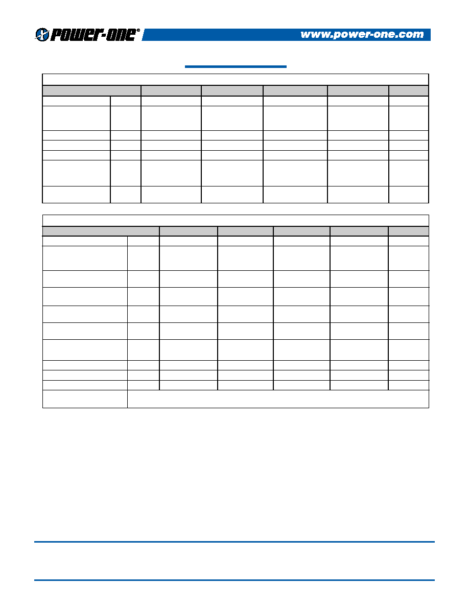
Selection Chart
Input Range
Output
Output
Model
VDC
VDC
mA MAX
Min
Max
Nominal
DFC25E12S3.3
9
18
3.3
7500
DFC25E24S5
18
36
5
6000
DFC25E48S5
36
72
5
6000
DFC25E48S12
36
72
12
2500
SIDE VIEW
0.040 (1.02) DIA
6 PLACES
0.00
0.43
0.38
2.50
3.00
(63.5)
(76.2)
BOTTOM VIEW
2
9
8
1
7
6
4
5
2.05
1.65
1.25
0.85
0.45
2.75
0.25
(1
1.4)
(21.6)
(31.8)
(42.0)
(52.1)
(6.3)
(70.0)
0.00
0.000
(1
1.0)
(9.65)
NOTES
(1) All parameters measured at 25∞C, nominal input voltage, and
full rated load unless otherwise noted.
(2) Derate linearly to 0 Watts at 105∞C ambient. Operation to +70∞C
ambient with externally supplied forced air cooling, 100LFM.
(3) Case is tied to -Input, Pin 1.
PIN CONNECTIONS
PIN NUMBER
PIN OUT
1
-INPUT
2
+INPUT
3
N/C
4
ON/OFF
5
TRIM
6
+OUTPUT
7
-OUTPUT
8
N/C
9
N/C
NOTE: All pins are 0.040"
diameter brass with tin plating.
Mechanical tolerances unless
otherwise noted:
X.XX dimensions: ±0.020 inches
X.XXX dimensions: ±0.005 inches
General Specifications (1)
All Models
Units
Isolation (3)
Isolation Voltage
Input to Output
12V, 24V Input
MIN
700
Volts
48V Input
MIN
1544
10µA Leakage
Input to Output Capacitance
TYP
700
pF
Remote ON/OFF
ON Logic Level or Pin Open
MIN
2.5
Volts
Off Logic Level or Tie to -Input
MAX
0.7
Volts
Converter Idle Current
TYP
10
mA
Output Trim Function
Input Resistance
TYP
40
k
Programming Range
MIN
±10
%
Environmental
Case Operating Range (2)
MIN
-25
∞C
MAX
+60
Case Functional Range
MIN
-40
∞C
MAX
+105
Storage Range
MIN
-45
∞C
MAX
+105
Thermal Impedance
TYP
10
∞C/Watt
General
MTBF (Calculated)
TYP
1,000,000
Hours
Unit Weight
TYP
2.6/71
oz/gm
1
Rev. 04/2000
NOTES
(1)
All parameters measured at Tc=25∞C, nominal input voltage and full rated load unless otherwise
noted.
(2)
Measurement bandwidth is 0-20 MHz for peak-peak measurements, 10 kHz to 1 MHz for RMS
measurements. Output noise is measured with a 0.01µF/100V ceramic capacitor in parallel with a
1µF/35V Tantalum capacitor, 1 inch from the output pins to simulate standard PCB decoupling
capacitance.
(3)
Short term stability is specified after a 30 minute warm-up at full load, constant line and recording
he drift over a 24 hour period.
(4) Per
ETSI-300-132
(5)
Recovery to within 1% in less than 1 millisecond after transient has been applied.
DFC25 SERIES APPLICATION NOTES:
External Capacitance Requirements
A low ESR external capacitance is required for operation of the DFC25 Series. For maximum
performance, it is recommended that the DFC25 Series use a capacitor of sufficient ripple current
capacity connected across the input pins, especially if a capacitive input source is farther than 1"
from the converter. To meet the reflected ripple requirements of the converter, an input impedance
of less than 0.09 Ohms at 200 kHz is required. External output capacitance is not required for
operation, however it is recommended that 1µF to 10µF of Tantalum and 0.001 to 0.1µF ceramic
capacitance be selected for each output to reduce system noise. Additional output capacitance may
be added for increased filtering, but should not exceed 400µF.
Remote ON/OFF Operation
The remote ON/OFF pin may be left floating if this function is not used. It is recommended to drive
this pin with TTL compatible circuitry. When the ON/OFF pin is pulled low with respect to the
-INPUT, the converter is placed in a low power drain state. The input capacitors are kept fully
charged in the OFF mode. For proper operation, this input may be driven from a logic gate directly.
The ON/OFF pin should never be pulled more than 0.3 volts below -INPUT or have a voltage
greater than +6 volts applied.
DFC25 SERIES ≠ SINGLE OUTPUT
Input Parameters (1)
Model
DFC25E12S3.3
DFC25E24S5
DFC25E48S5
DFC25E48S12
Units
Reflected Ripple (2)
TYP
330
230
150
150
mA
PP
Input Current
Full Load
TYP
2870
1563
781
762
mA
No Load
TYP
100
10
10
10
Inrush Current (4)
MAX
50
50
50
50
A
PK
Efficiency
TYP
72
80
80
82
%
Switching Frequency
TYP
150
150
150
150
kHz
Maximum Input
Overvoltage,
MAX
24
45
85
85
VDC
100ms Maximum
Turn-on Time,
1% Output Error
TYP
10
10
10
10
ms
Output Parameters (1)
Model
DFC25E12S3.3
DFC25E24S5
DFC25E48S5
DFC25E48S12
Units
Output Voltage
3.3
5
5
12
VDC
MIN
3.26
5.05
5.05
11.90
Output Voltage Accuracy
TYP
3.30
5.10
5.10
12.00
VDC
MAX
3.33
5.15
5.15
12.10
Rated Load Range
MIN
0.75
0.60
0.60
0.25
A
MAX
7.50
6.00
6.00
2.50
Load Regulation
10% Load - Max Load
TYP
1
1
1
1
%
Line Regulation
Vin = Min-Max VDC
TYP
0.2
0.2
0.2
0.2
%
Transient Response
25% Load Step (5)
TYP
2
2
2
2
%
Short Term Stability (3)
TYP
<0.05
<0.05
<0.05
<0.05
%/24Hrs
Long Term Stability
TYP
<0.1
<0.1
<0.1
<0.1
%/kHrs
Input Ripple Rejection
TYP
>40
>40
>40
>40
dB
Noise, Peak - Peak (2)
TYP
75
75
75
75
mV
PP
Temperature Coefficient
TYP
100
100
100
100
ppm/∞C
Short Circuit Protection
Continuous, Current Limit Protection
from +OUT to -OUT
2
NUCLEAR AND MEDICAL APPLICATIONS Power-One products are not authorized for use as critical components in life support systems, equipment used in hazardous environments,
or nuclear control systems without the express written consent of the President of Power-One, Inc.
TECHNICAL REVISIONS The appearance of products, including safety agency certifications pictured on labels, may change depending on the date manufactured. Specifications are
subject to change without notice.