 | –≠–ª–µ–∫—Ç—Ä–æ–Ω–Ω—ã–π –∫–æ–º–ø–æ–Ω–µ–Ω—Ç: GP1001-7R | –°–∫–∞—á–∞—Ç—å:  PDF PDF  ZIP ZIP |
1
www.power-one.com
Edition 6/10.2001
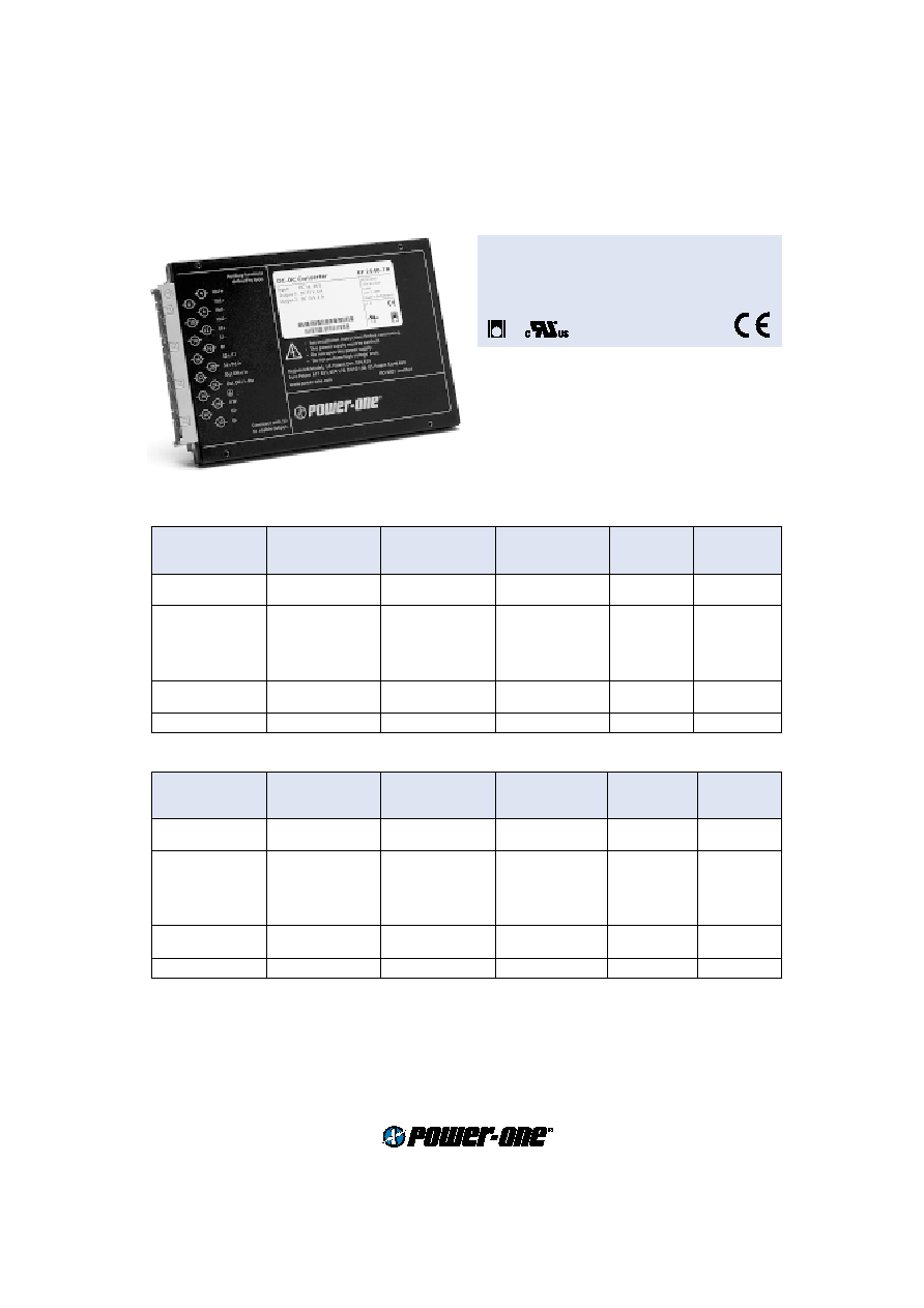
∑ Extremely slim case (4 TE), fully enclosed
∑ Extremely low inrush current, hot swappable
∑ Operating ambient temperature range
≠40...71
∞
C
with convection cooling
P Series
120...195 Watt DC-DC Converters
Input voltage up to 150 V DC
1 to 4 isolated outputs 3.3...96 V DC
4242V DC I/O electric strength test voltage
Selection chart
Output 1
Output 2
Output 3
Output 4
Type
Type
U
o nom
P
o nom
P
o max
U
o nom
P
o nom
P
o max
U
o nom
P
o nom
P
o max
U
o nom
P
o nom
P
o max
Input voltage
Input voltage
[V DC] [W]
[W]
[V DC] [W]
[W]
[V DC] [W]
[W]
[V DC] [W]
[W]
16...36 V DC 33.6...75 V DC
3.3
100
132
-
-
-
-
-
-
-
-
-
BP 1101-7R
CP 1101-7R
5.1
122
183
-
-
-
-
-
-
-
-
-
BP 1001-7R
CP 1001-7R
3.3
50
66
5.1
61
91
-
-
-
-
-
-
BP 2101-7R
CP 2101-7R
5.1
61
91
5.1
61
91
-
-
-
-
-
-
BP 2001-7R
CP 2001-7R
12
60
96
12
60
96
-
-
-
-
-
-
BP 2320-7R
CP 2320-7R
15
60
97.5
15
60
97.5
-
-
-
-
-
-
BP 2540-7R
CP 2540-7R
24
60
96
24
60
96
-
-
-
-
-
-
BP 2660-7R
CP 2660-7R
5.1
61
91
12
30
48
12
30
48
-
-
-
BP 3020-7R
CP 3020-7R
5.1
61
91
15
30
48
15
30
48
-
-
-
BP 3040-7R
CP 3040-7R
24
30
48
24
30
48
24
30
48
24
30
48
BP 4660-7R
CP 4660-7R
LGA
Output 1
Output 2
Output 3
Output 4
Type
Type
U
o nom
P
o nom
P
o max
U
o nom
P
o nom
P
o max
U
o nom
P
o nom
P
o max
U
o nom
P
o nom
P
o max
Input voltage
Input voltage
[V DC] [W]
[W]
[V DC] [W]
[W]
[V DC] [W]
[W]
[V DC] [W]
[W]
40...100.8VDC 66...150 V DC
3.3
100
132
-
-
-
-
-
-
-
-
-
DP 1101-7R
EP 1101-7R
5.1
122
183
-
-
-
-
-
-
-
-
-
DP 1001-7R
EP 1001-7R
3.3
50
66
5.1
61
91
-
-
-
-
-
-
DP 2101-7R
EP 2101-7R
5.1
61
91
5.1
61
91
-
-
-
-
-
-
DP 2001-7R
EP 2001-7R
12
60
96
12
60
96
-
-
-
-
-
-
DP 2320-7R
EP 2320-7R
15
60
97.5
15
60
97.5
-
-
-
-
-
-
DP 2540-7R
EP 2540-7R
24
60
96
24
60
96
-
-
-
-
-
-
DP 2660-7R
EP 2660-7R
5.1
61
91
12
30
48
12
30
48
-
-
-
DP 3020-7R
EP 3020-7R
5.1
61
91
15
30
48
15
30
48
-
-
-
DP 3040-7R
EP 3040-7R
24
30
48
24
30
48
24
30
48
24
30
48
DP 4660-7R
EP 4660-7R
2
www.power-one.com
Edition 6/10.2001
Cassette Style
P Series
Input
Input voltage
refer to selection chart
Output
Nominal output current
I
o1,2,3,4 nom
P
o nom
/Number of outputs/
U
o1,2,3,4 nom
Maximal output current
I
o1,2,3,4 max
P
o max
/Number of outputs/
U
o1,2,3,4 nom
Efficiency
U
i nom
,
I
o nom
up to 92 %
Voltage setting accuracy 1, 2
U
i nom
,
I
o nom
±
0.6 %
U
o1,2 nom
Voltage setting accuracy 3, 4
U
i nom
,
I
o nom
±
1.5 %
U
o3,4 nom
Worst case output voltage 1, 2
U
i min
...
U
i max
, 0...
I
o1,2 max
,
T
C min
...
T
C max
±
1.6 %
U
o nom
Minimum output current 1, 4
in parallel configuration not required
0 A
in individual or series configuration
5%
I
o1,4 nom
Minimum output current 2, 3
in parallel configuration not required
0 A
in individual or series configuration
5%
I
o2,3 nom
Load regulation output 4
I
o1,4 min
...
I
o1,4 max
typ. 100 m
∑ (
I
o1
...
I
o4
)
Load regulation output 3
I
o2,3 min
...
I
o2,3 max
typ. 100 m
∑ (
I
o2
...
I
o3
)
Output voltage switching noise
IEC/EN 61204, total, peak-peak
typ. 0.4%
U
o nom
Common power limitation
(
P
o1
+
P
o4
) rectangular U/I characteristic
typ. 130%
P
o max
/2
(
P
o2
+
P
o3
) rectangular U/I characteristic
typ. 130%
P
o max
/2
Protection
Input reverse polarity
built-in fuse
Input undervoltage lockout
typ. 90 %
U
i min
Input overvoltage lockout
typ. 110 %
U
i max
Input transient protection
varistor
Output
no-load, overload and short-circuit proof
Output overvoltage
varistor
typ. 125%
U
o nom
Overtemperature
switch-off with auto restart
T
C
typ. 100
∞
C
Output 1
Output 2
Output 3
Output 4
Type
U
o nom
P
o nom
P
o max
U
o nom
P
o nom
P
o max
U
o nom
P
o nom
P
o max
U
o nom
P
o nom
P
o max
Input voltage
[V DC]
[W]
[W]
[V DC]
[W]
[W]
[V DC]
[W]
[W]
[V DC]
[W]
[W]
21.6...50.4 V DC
3.3
100
132
-
-
-
-
-
-
-
-
-
GP 1101-7R
5.1
122
183
-
-
-
-
-
-
-
-
-
GP 1001-7R
3.3
50
66
5.1
61
91
-
-
-
-
-
-
GP 2101-7R
5.1
61
91
5.1
61
91
-
-
-
-
-
-
GP 2001-7R
12
60
96
12
60
96
-
-
-
-
-
-
GP 2320-7R
15
60
97.5
15
60
97.5
-
-
-
-
-
-
GP 2540-7R
24
60
96
24
60
96
-
-
-
-
-
-
GP 2660-7R
5.1
61
91
12
30
48
12
30
48
-
-
-
GP 3020-7R
5.1
61
91
15
30
48
15
30
48
-
-
-
GP 3040-7R
24
30
48
24
30
48
24
30
48
24
30
48
GP 4660-7R

3
www.power-one.com
Edition 6/10.2001
Control
Output voltage adjustment
output 1, 4
60/80...110%
U
o nom
Inhibit on input side
TTL input, output(s) disabled if open circuit
Status indication
LEDs: In OK, Out OK
Output good signal (Out OK)
isolated open collector signal
Safety
Approvals
EN 60950, UL 1950, CSA C22.2 No. 950
Class of equipment
class I
Protection degree
IP 40
Electric strength test voltage
I/case, O/case, Out OK/case
1.5 kV AC
I/O, Out OK/I, Out OK/O
4242 V DC / 3 kV AC
O/O
500 V DC
EMC
Electrostatic discharge
IEC/EN 61000-4-2, level 4 (8/15 kV)
criterion B
Electromagnetic field
IEC/EN 61000-4-3, level 3 (10 V/m)
criterion A
Electr. fast transients/bursts
IEC/EN 61000-4-4, output/input, level 3/4 (2/4 kV)
criterion B
Surge
IEC/EN 61000-4-5, input, level 2/3 (1/2 kV)
criterion B
Conducted disturbances
IEC/EN 61000-4-6, level 2/3 (3/10 V)
criterion A
Electromagnetic emissions
CISPR 22/EN 55022, conducted
class B
Environmental
Operating ambient temperature
U
i nom
,
P
o nom
, convection cooled
≠25...71
∞
C
Operating case temperature
T
C
U
i nom
,
P
o nom
/
P
o max
≠25...95
∞
C
Storage temperature
non operational
≠40...100
∞
C
Damp heat
IEC/EN 60068-2-3, 93 %, 40
∞
C
56 days
Vibration, sinusoidal
IEC/EN 60068-2-6, 10...60/60...2000 Hz
0.35 mm/5 g
n
Shock
IEC/EN 60068-2-27, 11 ms
50 g
n
Bump
IEC/EN 60068-2-29, 11 ms
25 g
n
Random vibration
IEC/EN 60068-2-64, 20...500 Hz
4.9 g
n rms
Options
Extended temperature range
≠40...71
∞
C, ambient, operating
-9
Out OK output
excludes option i
D
Current sharing
T
Inhibit on output side
excludes option D
i
Synchronisation
W
Heat Sink
B1
P Series
120...195 Watt DC-DC Converters
4
www.power-one.com
Edition 6/10.2001
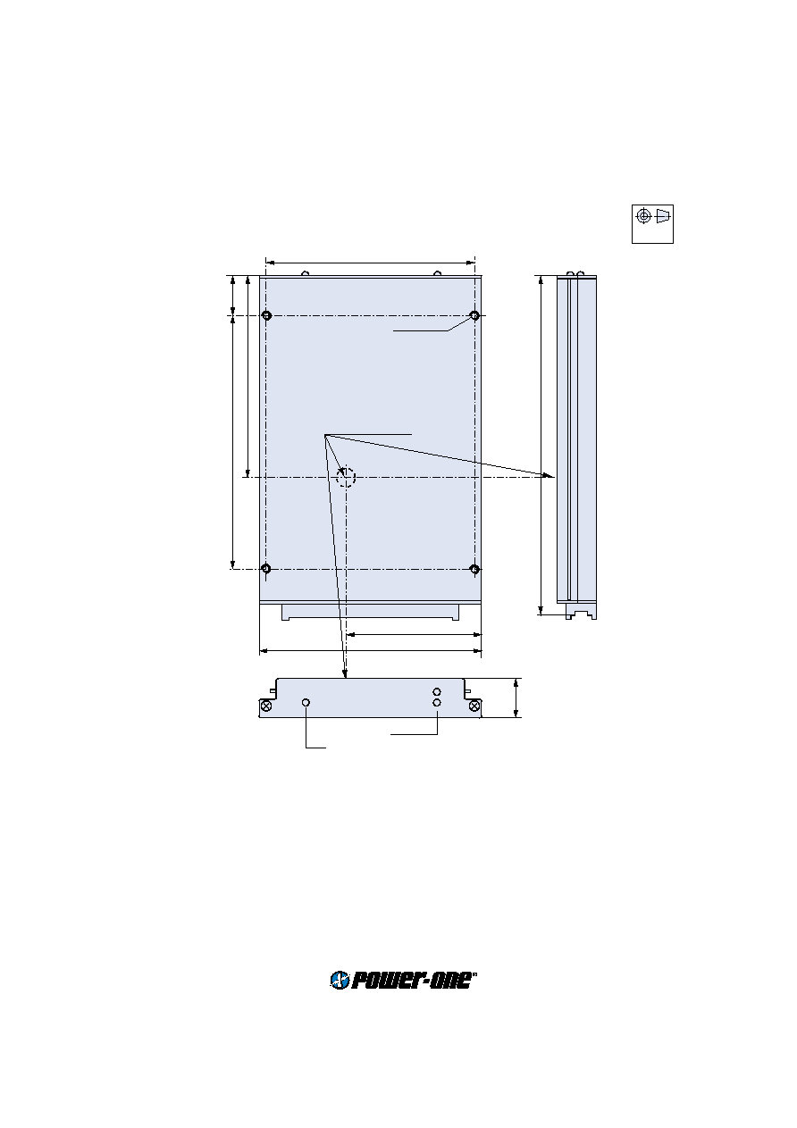
Mechanical data
Tolerances
±
0.3 mm (0.012") unless otherwise indicated.
European
Projection
104 (4.09")
70 (2.76")
111 (4.37")
20 (0.79")
100 (3.94")
127 (5")
19.8
(0.78")
M3; through
Measuring point of
case temperature
T
C
LED "Out OK"
LED "In OK"
171.93 (DIN 41494) (6.77")
S09099
Cassette Style
P Series
5
www.power-one.com
Edition 6/10.2001
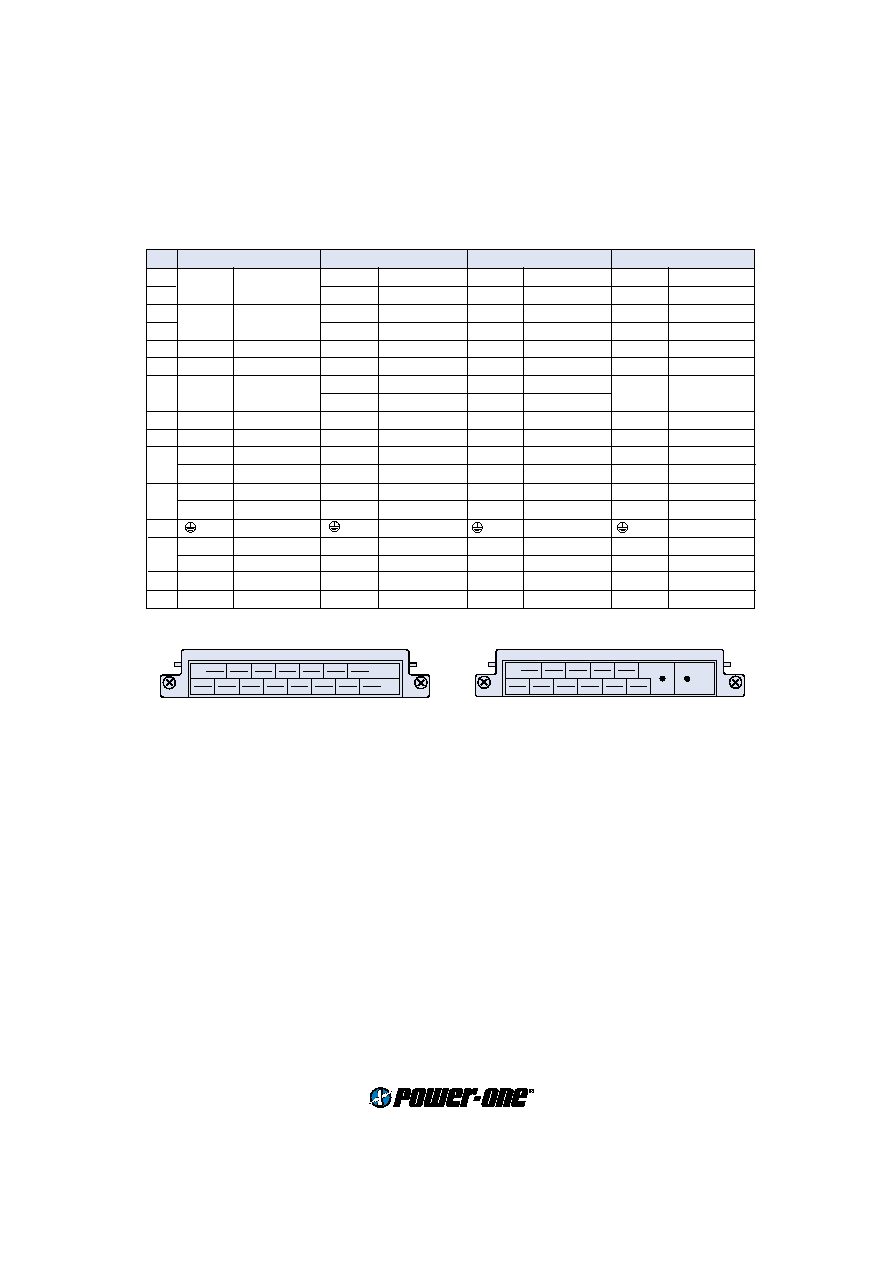
30
26
22
18
14
10
6
S10025
32
28
24
20
16
12
8
4
32
28
24
20
16
12
4/6
30
26
22
18
14
8/10
S10051
Pin allocation
Pin
P 1000
P 2000
P 3000
P 4000
4
Vo1+
Output 1
Vo1+
Output 1
Vo1+
Output 1
Vo1+
Output 1
6
Vo2+
Output 2
Vo2+
Output 2
Vo2+
Output 2
8
Vo1≠
Output 1
Vo1≠
Output 1
Vo1≠
Output 1
Vo1≠
Output 1
10
Vo2≠
Output 2
Vo2≠
Output 2
Vo2≠
Output 2
12
S+
Sense
S1+
Sense 1
S1+
Sense 1
Vo4+
Output 4
14
S≠
Sense
S1≠
Sense 1
S1≠
Sense 1
Vo4≠
Output 4
16
R
Control of
U
o
R1
Control of
U
o1
R1
Control of
U
o1
R1/4
Control of
U
o1/4
T1
Current sharing T1
Current sharing
18
T
Current sharing S2+
Sense 2
Vo3+
Output 3
Vo3+
Output 3
20
n.c.
Not connected S2≠
Sense 2
Vo3+
Output 3
Vo3+
Output 3
22
Out OK+ Output good
Out OK+ Output good
Out OK+ Output good
Out OK+ Output good
i+
Inhibit second.
i+
Inhibit second.
i+
Inhibit second.
i+
Inhibit second.
24
Out OK≠ Output good
Out OK≠ Output good
Out OK≠ Output good
Out OK≠ Output good
i≠
Inhibit second.
i≠
Inhibit second.
i≠
Inhibit second.
i≠
Inhibit second.
26
Prot. ground
Prot. ground
Prot. ground
Prot. ground
28
i
Inhibit
i
Inhibit
i
Inhibit
i
Inhibit
W
Synchronisat.
W
Synchronisat.
W
Synchronisat.
W
Synchronisat.
30
Vi+
Input
Vi+
Input
Vi+
Input
Vi+
Input
32
Vi≠
Input
Vi≠
Input
Vi≠
Input
Vi≠
Input
P Series
120...195 Watt DC-DC Converters
Accessories
Additional external heat sinks for operation above
P
o nom
or
T
A max
Front panels for 19" rack mounting in 3U or 6U configuration (Schroff/Intermas)
Mating H15 connectors with screw, solder, fast-on or press-fit terminals
Mechanical mounting supports for chassis, DIN-rail and PCB mounting