
Data Sheet
HBT Series ≠ Half-Brick DC/DC Converter
48V Input
60 Watt Triple Output
REV. 10/01 Page 1 of 12
www.power-one.com
Applications
∑
Distributed power architectures
∑
Data and Telecommunications Equipment
∑
Computer
Equipment
∑
Distributed power architectures
∑
LAN/WAN
applications
∑
Data processing applications
Features
∑
60 Watts maximum total output power
∑
Three fully isolated outputs 5V/12V/12V
∑
5V output provides up to 12 Amps
∑
(2) 12V outputs each provide up to 2.5 Amps
∑
Excellent
cross
regulation
∑
Low profile ≠ 12.7 mm
∑
High efficiency topology, 88% Typical
∑
Output
overcurrent
& overvoltage protection
∑
Overtemperature
protection
∑
Set
point
accuracy
±
2.0%
∑
1500V Input/output isolation meets basic
insulation requirements
∑
UL 1950 Recognized, CSA 22.2 No. 950-95
certified; TUV IEC950
Description
The HBT17ZGHH DC-DC Converter operates over an input voltage range of 33Vdc to 75Vdc and provides
three isolated output voltages. The 5V output can provide a full 60W (12 Amperes) of output power and each
12V output can provide up to 30W (2.5 Amperes) of output power. The input is fully isolated from each
output and each output is isolated from one another. The isolation of each output provides flexible output
configurations and separate output returns, which are important in preventing cross-interference between
different loads in system applications. The module has a typical full load efficiency of 88%.
The two-board construction optimizes thermal performance. Power devices are connected to an Integrated
Metal Substrate base plate to minimize thermal impedance and a separate control board is physically
isolated from the hotter IMS board. This approach allows for lower average component temperatures on the
control board and increases the overall reliability. The comprehensive standard feature set includes remote
on/off, and output trim.
Selection Chart
Model
Input
voltage
range,
VDC
Input
current,
max,
ADC
Output
voltage, VDC
Output
rated
current,
ADC
Output Ripple
and Noise,
mV p-p
Efficiency
%
HBT060ZGHH-A
33-75
3.0
5.0/12.2/12.2
12/2.5/2.5
125/150/150
88
Data Sheet
HBT Series ≠ Half-Brick DC/DC Converter
48V Input
60 Watt Triple Output
REV. 10/01 Page 2 of 12
www.power-one.com
Table 1. Absolute Maximum Ratings
Parameter
Symbol
Min
Max
Units
Input Voltage
Continuous
Transient
Vi
Vi
-
-
80
100
Vdc
Vdc
Operating Baseplate Temperature
Note 1
Tb
-40
+100
∞
C
Storage Temperature
Tstg
-55
+125
∞
C
Input to Output Isolation
-
-
1500
Vdc
Output Short Circuit Duration
-
-
Continuous
-
Total Output Power
Pomax
-
60
W
No Load Power Dissipation
-
6
W
Electrical Specifications
Unless otherwise indicated, specifications apply over all input voltages, resistive load, and Tbp=+40
∞
C.
Table 2. Input Specifications
Parameter
Symbol
Min
Typ
Max
Units
Voltage Range
Vi
33
48
75
Vdc
Maximum Input Current
Ii
-
-
3
A
Input Ripple Rejection (120Hz)
-
60
-
dB
Inrush Transient
-
-
1
A
2
s
Input Reflected Ripple (See Fig.1)
100
MA
p-p
Fusing considerations
Caution: This DC-DC converter is not internally fused. An external input fuse must always be used.
Table 3. Output Specifications
Parameter
Symbol
Min
Typ
Max
Units
Output Power
Po1
Po2
Po3
-
-
-
-
-
-
60
30
30
W
W
W
Output Voltage Set Point
(Vi=48Vdc, Io1=6A,
Io2=Io3=1.25A)
Vo1
Vo2, Vo3
4.9
11.834
5.0
12.2
5.1
12.566
Vdc
Vdc
Output Line Regulation:
(Vi=Vi,min to Vi,max)
(Io1=6A, Io2=Io3=1.25A)
Vo1
-
0.02
0.1
%
Output Load Regulation:
(0.5A to Iomax)
Vo1
-
0.2
0.4
%
Output Load Regulation:
(Vi = Vi.min to Vi,max)
(All Loading Conditions)
Vo2, Vo3
10.5
-
13.5
Vdc
Output Temperature Regulation:
(Tbase =-40
∞
C to +100
∞
C)
All Outputs
-
0.02
0.05
%/
∞
C
Output Current
(Maximum output power limited to
60W)
Io1
Io2
Io3
0.5
0
0
6
1.25
1.25
12
2.5
2.5
A
A
A

Data Sheet
HBT Series ≠ Half-Brick DC/DC Converter
48V Input
60 Watt Triple Output
REV. 10/01 Page 3 of 12
www.power-one.com
Parameter
Symbol
Min
Typ
Max
Units
Output Ripple (See Figure 2)
(DC to 20MHz)
(Io1 = 6A, Io2,Io3 = 1.25A)
Vo1
Vo2
Vo3
-
-
-
125
150
150
200
250
250
mVp-p
mVp-p
mVp-p
Output Current Limit inception
(Other outputs at no load)
Io1
Io2
Io3
-
-
-
16
6.5
6.5
18
7
7
A
A
A
Transient Response
(50% to 100% Load Step,
Io/
t=0.1A/uSec)
Peak Deviation
Settling Time (Vo, 1% of Vo1)
Vo1
-
-
75
50
200
150
mV
µ
Sec
Overvoltage Limit
Vo1
5.9
-
6.5
Vdc
Table 4. Feature Specifications
Parameter
Symbol
Min
Typ
Max
Units
Remote On/Off, Primary side
Vlow
Vhigh
Sink Current-Logic Low
-
-
-
-
-
-
1
7
2
V
V
mA
Turn-on time (Within 1% Vonom)
-
3.5
5
mSec
Switching Frequency
-
440
-
KHz
Output Voltage Adjust (Vo1 only)
Vo,adj
8
-
9
%Vo,nom
Thermal Shutdown
+105
+115
∞
C
Undervoltage Lockout
Turn-on
Turn-off
-
28
32
30
32.9
-
V
V
Table 5. Environmental
Parameter
Min
Typ
Max
Units
Operating Baseplate Temperature
-40
-
+100
∞
C
Operating Humidity (non-condensing)
95
%
Storage Humidity (non-condensing)
95
%
Table 6. Isolation Specifications
Parameter
Min
Typ
Max
Units
Input to Each Output
1500
-
-
Vdc
Input to Baseplate
1500
-
-
Vdc
Output to Output
500
-
-
Vdc
Resistance, Input - Output
10
-
-
M
Capacitance, Input - Output
-
1000
-
pF
Data Sheet
HBT Series ≠ Half-Brick DC/DC Converter
48V Input
60 Watt Triple Output
REV. 10/01 Page 4 of 12
www.power-one.com
Table 7. EMI & Regulatory Agency Compliance
Conducted Emissions
(With input filter configuration in Figure 3.)
CISPR 22 class A
Safety ≠ Basic
UL60950 Recognized, CAN/CSA C22.2 No.
60950-00 Recognized
Table 8. General Specifications
Parameter
Min
Typ
Max
Units
Efficiency
(Vi=48Vdc, Io1=6A, Io2=Io3=1.25A)
86
87.5
-
%
Calculated MTBF (Po=60W, Tbp=40
∞
C)
-
900
-
kHrs
Table 9. Physical
Parameter
Min
Typ
Max
Units
Dimensions
2.30(58.4)
2.40(60.9 )
0.50(12.70 )
In. (mm)
Weight
2.4(68)
oz(g)
Markings & labeling
Includes Part Number, Power-One Logo, Date Code and
Country of Manufacture

Data Sheet
HBT Series ≠ Half-Brick DC/DC Converter
48V Input
60 Watt Triple Output
REV. 10/01 Page 5 of 12
www.power-one.com
Feature Descriptions
Output Over-voltage Clamp
The output overvoltage clamp consists of a
separate control loop, independent of the primary
control loop. This control loop has a higher
voltage set point than the primary loop. In a fault
condition which creates an excessive output
voltage, the converter goes into "Hiccup Mode"
(turns off and restarts periodically in a pre-
programmed fashion), and the output overvoltage
clamp ensures that the output voltage does not
exceed Vo, clamp, max. This secondary control
loop provides a redundant voltage control
mechanism that prevents catastrophic voltages
from occurring on the output under any single-
fault condition.
Output Current Protection
To provide protection in an output overload or
short circuit condition, the converter is equipped
with a current limiting circuit, which can protect
the converter from damage under a fault condition
indefinitely. At the current-limit inception point due
to an output overload, the converter goes into
"Hiccup Mode" and limits both the peak output
current and the duration of the operation. The
converter recovers automatically to its normal
operation once the output overload or short circuit
is removed.
Enable
Two enable options are available-Positive Logic
and Negative Logic. Positive Logic turns the
converter on when a logic-high is present at the
enable pin, and turns the converter off when a
logic-low is present at the enable pin. Negative
Logic turns the converter off when a logic-high is
present at the enable pin, and turns the converter
on when a logic-low is present at the enable pin.
Output Voltage Adjustment
Output voltage adjustment is accomplished by
connecting an external resistor between the Trim
Pin and the +Vo1 or ≠Vo1 Pins.
With an external resistor (R
adj-down
) between the
Trim Pin and +Vo1 Pin the output voltage set
point (Vo,adj) decreases. The following equation
determines the required external resistor value to
obtain an adjusted output voltage:
Note: Output Vo1 is the only trimable output.
Output Vo2 and Vo3 only follow how Vo1 is
trimmed.
Radj dn
Vo adj
D
-
,
(
) A
Vo nom
Vo
-
,
adj
,
B
-
ohm
,
Where R
adj-down
is the trim-down resistance value
and A, B, and D are constants defined in Table
10.
With an external resistor (R
adj-up
) between the
Trim Pin and ≠Vo1 Pin the output voltage set
point (Vo,adj) increases. The following equation
determines the required external resistor value to
obtain an adjusted output voltage:
Raj up
A D
Vo adj
D
-
,
(
)
C
-
B
-
ohm
,
Where R
adj-up
is the trim-up resistance value and
A, B, C, and D are constants defined in Table 10:
A
B
C
D
4990
25500
2.5
2.5
Table 10 Output Adjustment Variables.
Data Sheet
HBT Series ≠ Half-Brick DC/DC Converter
48V Input
60 Watt Triple Output
REV. 10/01 Page 6 of 12
www.power-one.com
Thermal Considerations
The power converter operates in various thermal
environments. Sufficient cooling should be
provided to help ensure reliable operation of the
converter. Major heat-dissipating components are
thermally coupled to the metal substrate. Heat is
removed from the metal substrate by conduction,
convection, and radiation to the surrounding
environment. Proper cooling can be verified by
measuring the temperature of the substrate. It is
recommended the substrate temperature be
maintained below 100 ∫C for reliable operation.
When necessary, an additional heat sink can be
attached to the substrate to achieve desired
thermal performance.
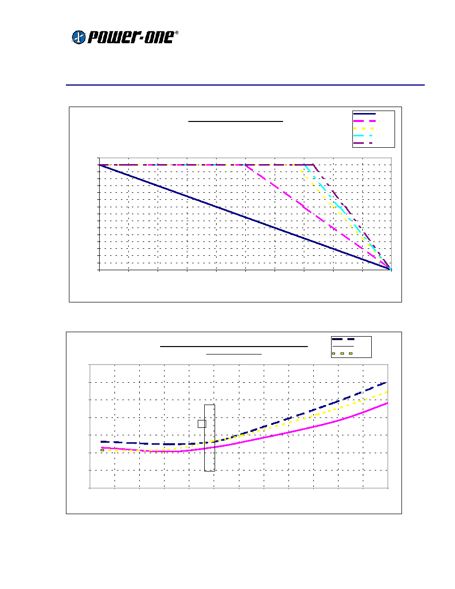
Heat Transfer Characteristics
Increasing airflow over the converter enhances
the heat transfer via convection. Figure 4 shows
the maximum power that can be dissipated by the
converter without exceeding the maximum
substrate temperature versus local ambient
temperature (T
A
).
Use of Figures 4 and 5 to properly determine
proper airflow for cooling the converter at a given
output power and a maximum ambient
temperature is illustrated in the following example.
Example
What is the minimum airflow required for the
device operating with an input voltage range of
33V to 75V, an output power of 60 W, at a
maximum ambient temperature of 70 ∫C?
Solution:
Given: Vi = 33V-75V, Po = 60 W, T
A
= 70 ∫C.
Step 1 (Determining P
D
): From Figure 5,
the maximum power dissipation is 12W (occurs at
Vin = 33V)
Step 2 (Determine airflow): From Figure
4, to maintain the substrate temperature below
100C, the airflow has to be greater than 160LFM
(interpolated between curves for 100LFM and
200LFM).
Test Setup
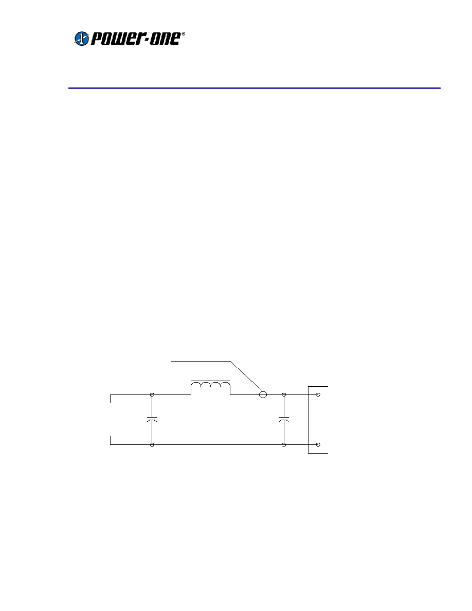
Figure 1 Input Reflected Ripple Current Test Set-up:
Note: Measure input reflected-ripple current with a simulated inductance (Ltest) of 12 uH. Capacitor Cs offsets possible
battery impedance. Measure current as shown above.
BATTERY
Cs 220 uF
ESR < 0.1 OHM
@ 20 ∫C, 100
kHz
Ltest
12 uH
22uF
ESR < 0.7 OHM
@ 20 ∫C, 100 kHz
Vi(+)
Vi(-)
TO CURRENT PROBE
Data Sheet
HBT Series ≠ Half-Brick DC/DC Converter
48V Input
60 Watt Triple Output
REV. 10/01 Page 7 of 12
www.power-one.com
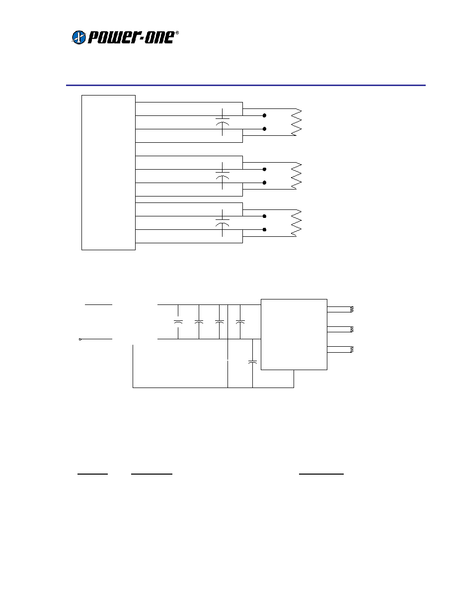
H B T 1 7 Z G H H - A
C 1
V i n +
V i n -
+
-
V I N
C 2
F C 1 0 0 V 1 0
C A S E
G N D
C 3
C 4
C 5
C 6
V o 1
- V o 1
V o 2
- V o 2
V o 3
- V o 3
L O A D 1
L O A D 2
L O A D 3
Figure 2: Output Ripple Measurement Test Set-up:
Note: Use a 0.1uf ceramic capacitor. Scope measurement should be made using a BNC socket. Position
loads between 51 mm and 76 mm (2 in. and 3 in.) from module.
Figure 3: Input filter configuration required to meet CISPR 22 Class A for Conducted Emissions.
Part List for Input Filter
Ref. Des
Description
Manufacture
C1, 2
0.47uF @100V MLC Capacitor (1812)
AVX or Equivalent (Equiv.)
C3
100uF @ 100V Alum. Electrolytic Capacitor
Nichicon NRSZ Series or Equiv.
C4
22uF@ 100V Alum. Electrolytic Capacitor
United Chemicon KMG Series or Equiv.
C5, 6
0.01uF MLC Capacitor
AVX or Equiv.
F1
FC100V10 Input Filter Module
Power-One
DUT
LOAD1
LOAD2
LOAD3
0.1uf
ceramic
0.1uf
ceramic
0.1uf
ceramic
SCOPE
SCOPE
SCOPE
COPPER STRIPS (2 to 3 inches)
+Vo1
-Vo1
+Vo2
-Vo2
+Vo3
-Vo3
Data Sheet
HBT Series ≠ Half-Brick DC/DC Converter
48V Input
60 Watt Triple Output
REV. 10/01 Page 8 of 12
www.power-one.com
Thermal Considerations
Figure 4. Maximum Allowable Power Dissipation to maintain substrate at 100
∫
C
Figure 5. Power Dissipation vs. Output Power (substrate temperature maintained at 100 ∫C)
HBT060ZGHH-A - Power Derating
0
1
2
3
4
5
6
7
8
9
10
11
12
13
14
15
16
0
10
20
30
40
50
60
70
80
90
100
Ambient Temperature (C)
Power Dissipation (W)
Natural
100 LFM
200 LFM
300 LFM
400 LFM
HBT060ZGHH-A Power Dissipation vs Output Power
Baseplate @ 100 ∞C
0
2
4
6
8
10
12
14
0
5
10
15
20
25
30
35
40
45
50
55
60
Output Power (W)
Power Dissipation (W)
Vin,min
Vin,nom
Vin,max
Data Sheet
HBT Series ≠ Half-Brick DC/DC Converter
48V Input
60 Watt Triple Output
REV. 10/01 Page 9 of 12
www.power-one.com
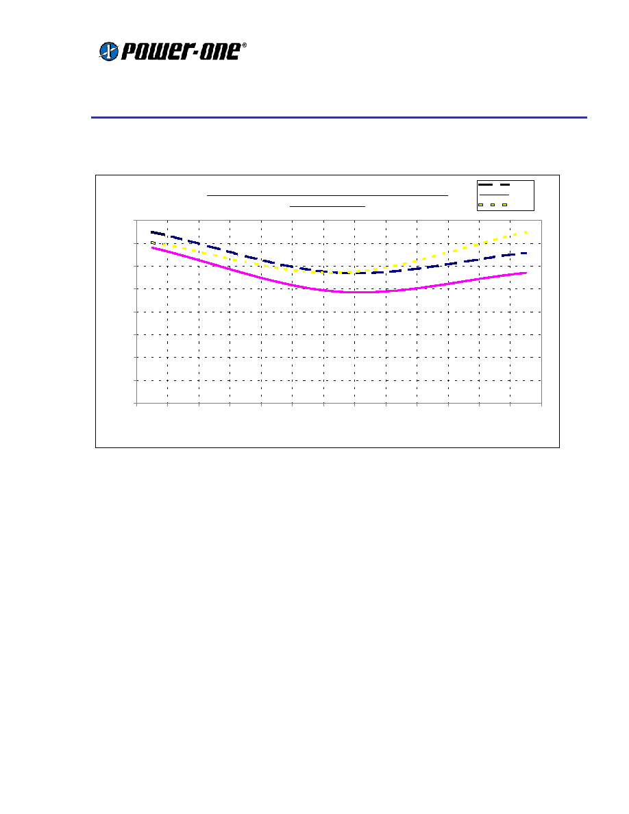
Thermal Considerations (continued)
Figure 6. Power Dissipation vs. Full Load Distribution
HBT060ZGHH-A - Power Dissipation vs Full Load Distribution
Baseplate @ 100∞C
0
2
4
6
8
10
12
14
16
0.5/5
1/4.6
2/4.2
3/3.8
4/3.3
5/2.9
6/2.5
7/2.1
8/1.7
9/1.3
10/0.8
11/0.4
12/0
Output Load - Io1/Io2+Io3 (A)
Power Dissipation (W)
Vin,min
Vin,nom
Vin,max
Data Sheet
HBT Series ≠ Half-Brick DC/DC Converter
48V Input
60 Watt Triple Output
REV. 10/01 Page 10 of 12
www.power-one.com
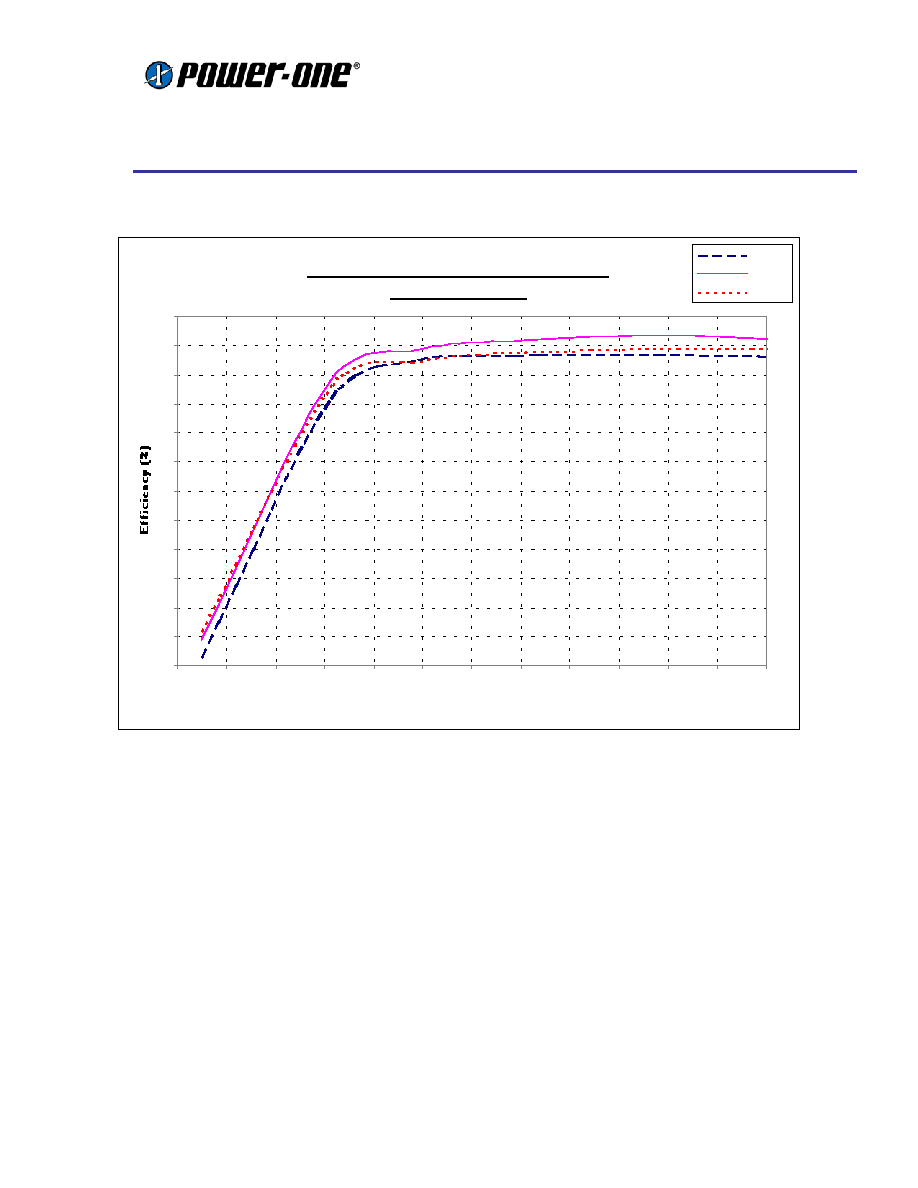
Characteristic Curves
T
A
= 25 ∫C, nominal input voltage, and rated load unless otherwise specified.
HBT060ZGHH-A Efficiency vs Output Power
Baseplate @ 100 ∞C
30
35
40
45
50
55
60
65
70
75
80
85
90
0
5
10
15
20
25
30
35
40
45
50
55
60
Output Power ( W)
Vin,min
Vin,nom
Vinmax
Figure 7. Efficiency vs. Output Power
Data Sheet
HBT Series ≠ Half-Brick DC/DC Converter
48V Input
60 Watt Triple Output
REV. 10/01 Page 11 of 12
www.power-one.com
Characteristic Curves
T
A
= 25 ∫C, nominal input voltage, and rated load unless otherwise specified.
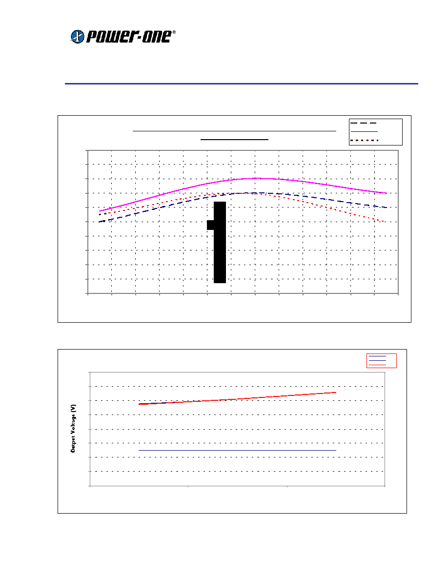
Figure 8 ≠ Efficiency vs. FL Power Distribution
H B T 0 6 0 Z G H H - A T y p i c a l C r o s s R e g u l a t i o n
0
2
4
6
8
10
12
14
16
0.5/5
6/2.5
12/0
V o1
Vo2
Vo3
HBT060ZG HH-A E fficiency vs Full Load Pow er Distribution
Baseplate @ 100 ∞C
70
72
74
76
78
80
82
84
86
88
90
0.5/5
1/4.6
2/4.2
3/3.8
4/3.3
5/2.9
6/2.5
7/2.1
8/1.7
9/1.3
10/0.8
11/0.4
12/0
Output P ower (W )
Efficiency (%)
V in,m in
V in,nom
V in,m ax
Figure 9. Typical Cross Regulation
Data Sheet
HBT Series ≠ Half-Brick DC/DC Converter
48V Input
60 Watt Triple Output
REV. 10/01 Page 12 of 12
www.power-one.com
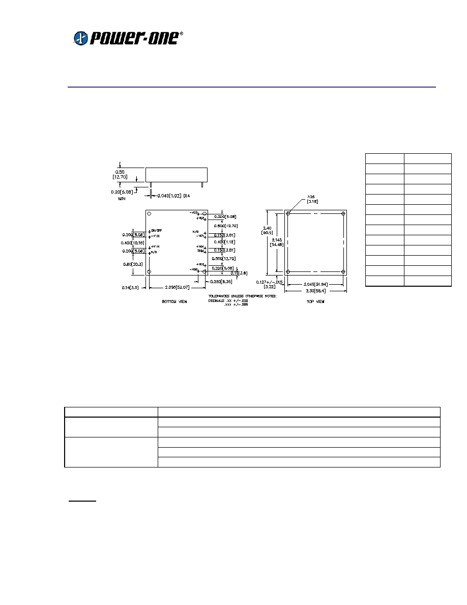
Mechanical Drawing
PIN VIEW
Tolerances:
.xx
±
.020 (.5)
.xxx
±
.010 (.25)
Pin diameter:
±
.0.002 (.05)
Ordering Information
Options
Suffixes to add to part number
Positive- Standard, no suffix required
Remote On/Off
Negative- Add "N" suffix
0.18"- Standard, no suffix required
0.11"- Add "8" suffix
Pin Length
0.15"- Add "9" suffix
Notes
1.
Consult factory for the complete list of available options.
2.
Power-One products are not authorized for use as critical components in life support systems, equipment used in hazardous
environments, or nuclear control systems without the express written consent of the President of Power-One, Inc.
3.
Specifications are subject to change without notice.
Pin
Function
1
On/off
2
-Vin
3
+Vin
4
NC
5
-Vo2
6
+Vo2
7
Trim
8
+Vo1
9
-Vo1
10
NC
11
+Vo3
12
-Vo3