3
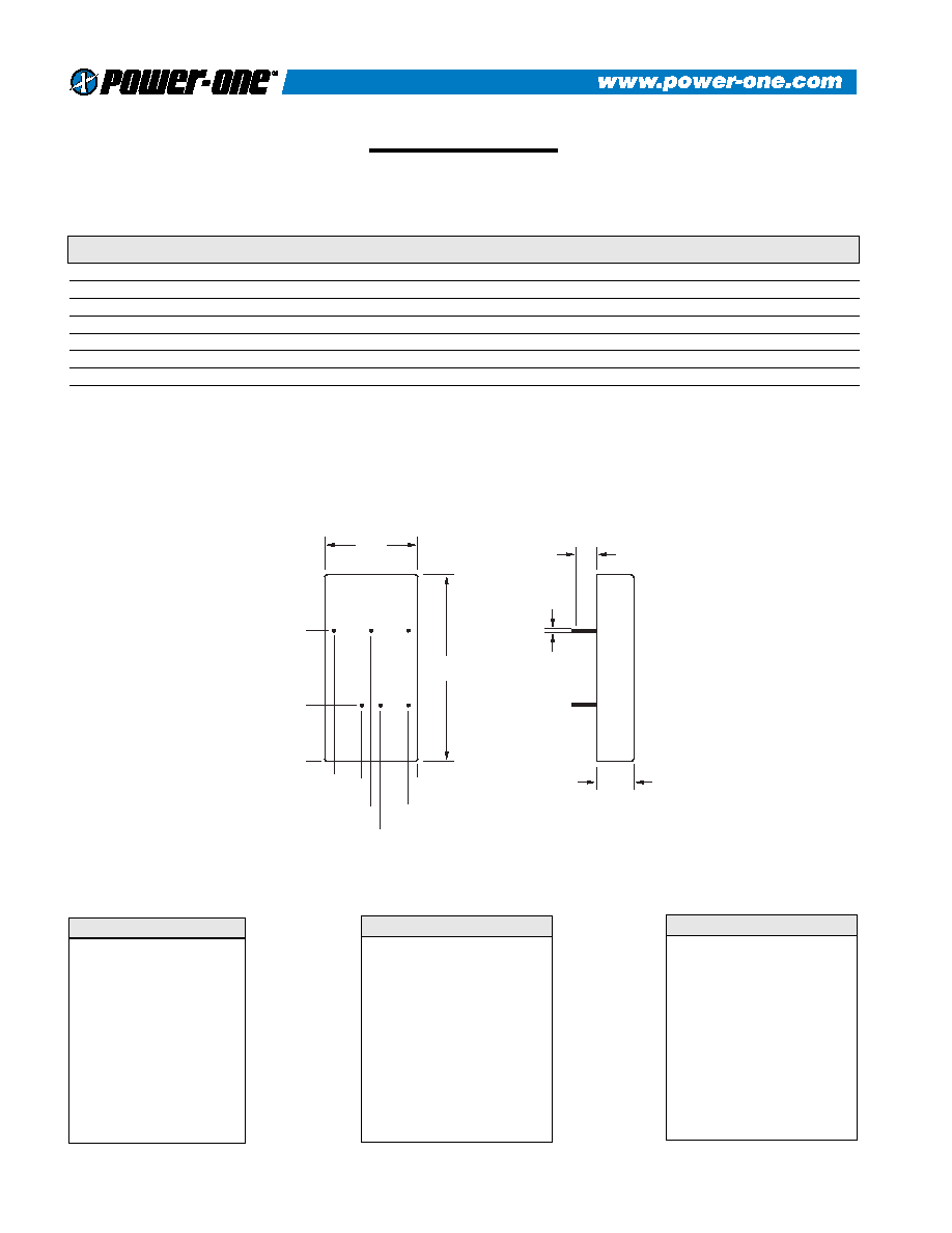
IAS010YG
40
45
50
55
60
65
70
75
80
85
10
20
30
40
50
60
70
80
90
100
LOAD %
EFFICIENCY
%
EFF. (18v)
EFF. (24v)
EFF. (36v)
Setpoint Accuracy
±1%
Line Regulation Vin Min. - Vin Max., Iout Rated
±0.2% Vout
Load Regulation Iout Min. - Iout Max., Vin Nom.
±0.5% Vout
Minimum Output Current
10 % Iout Rated
Dynamic Regulation, Loadstep
25% Iout
Pk Deviation
4% Vout
Settling Time
500 mS
Voltage Trim Range
±10%
Short Circuit / Overcurrent Protection
Shutdown / Hiccup
Current Limit Threshold Range, % of Iout Rated
110 - 140%
TECHNICAL SPECIFICATIONS
IAS DC/DC converters provide up to 12 watts of output power in
an industry-standard package and footprint. With a maximum case
temperature of 100∞C, the IAS is well suited for the most
demanding applications. The IAS features 1500 VDC isolation,
short circuit, and overtemperature protection, as well as six-sided
shielding. The IAS is available with optional enable and voltage
trim pins. Please see the IAD series for dual output applications.
∑ Industry Standard
Package
∑ Industry Standard
Footprint
∑ Up to 12W Output
∑ 100∞C Case Operation
∑ Optional Trim and
Enable
∑ Wide Range Input
∑ 1500V Isolation
∑ Short Circuit Protection
DESCRIPTION
FEATURES
Efficiency vs. Load (24V Input)
Turn-On Time
10 mS
Remote Shutdown
Positive Logic
Switching Frequency
375 kHz
Isolation
Input - Output
1500 VDC
Input - Case (24 Vin)
1050 VDC
Output - Case (48 Vin)
500 VDC
Temperature Coefficient
±0.03%/∞C
Case Temperature
Operating Range
-40 To +100∞C
Storage Range
-55 To +115∞C
Humidity Max., Non-Condensing
95%
Vibration, 3 Axes, 5 Min Each
5 g, 10 - 55 Hz
MTBF (Bellcore Tr-nwt-000332)
2.1 X 10⁶ hrs
Safety
UL, cUL, VDE
Weight (Approx.)
1.0 oz
MTBF predictions may vary slightly from model to model.
Specifications typically at 25∞C, normal line, and full load,
unless otherwise stated.
Soldering Conditions: I/O pins, 260∞C, ten seconds; fully
compatible with commercial wave-soldering equipment.
Safety: Agency approvals may vary from model to model.
Please consult factory for specific model information.
Units are water-washable and fully compatible with
commercial spray or immersion post wave-solder washing
equipment.
Output
General
Notes
IAS SERIES - 12 WATT
Voltage Range
24 VDC Nominal
18 - 36 VDC
48 VDC Nominal
34 - 75 VDC
Reflected Ripple
25 mA
Input Reverse Input Current
Shunt Diode
Input
REV. 08/30/01

5
When ordering equipment options, use the following suffix information. Select the option(s) that you prefer and add
them to the model number. Example ordering options are located below the options table.
OPTION
SUFFIX
APPLICABLE SERIES
REMARKS
Negative Logic
N
HAS, HBD, HBS, HES, HLS, LES,
QBS, QES, QLS, TES, TQD
TTL Low Turns Module ON
TTL High Turns Module OFF
Lucent-Compatible Trim
T
HAS, HBD, HBS, HES, HLS, QBS,
QES, QLS
Terminal Strip
TS
XWS, XWD, XWT
Trim
1
IAS, LES
Enable
2
IAD, IAS, LES, SMS
Trim and Enable
3
IAS, LES
Current Share
4
SMS
Headerless
Y
Encapsulated EWS, IWS, OWS
PIN LENGTH AND HEATSINK
OPTIONS
Standard Pin Length is 0.180
(4.6mm)
0.110 (2.8mm) Pin Length
8
All Units (Except SMS)
0.150 (3.8mm) Pin Length
9
All Units (Except SMS)
0.24 (6.1mm) Horizontal Heatsink
1H
All Units (Except DIP, HLS, HLD, QLS,
SIP, SM, TLD, and TKD Packages)
Includes Thermal Pad
0.24 (6.1mm) Vertical Heatsink
1V
All Units (Except DIP, HLS, HLD, QLS,
SIP, SM, TLD, and TKD Packages)
Includes Thermal Pad
0.45 (11.4mm) Horizontal
Heatsink
2H
All Units (Except DIP, HLS, HLD, QLS,
SIP, SM, TLD, and TKD Packages)
Includes Thermal Pad
0.45 (11.4mm) Vertical Heatsink
2V
All Units (Except DIP, HLS, HLD, QLS,
SIP, SM, TLD, and TKD Packages)
Includes Thermal Pad
0.95 (24.1mm) Horizontal
Heatsink
3H
All Units (Except DIP, HLS, HLD, QLS,
SIP, SM, TLD, and TKD Packages)
Includes Thermal Pad
0.95 (24.1mm) Vertical Heatsink
3V
All Units (Except DIP, HLS, HLD, QLS,
SIP, SM, TLD, and TKD Packages)
Includes Thermal Pad
Example Options:
HBS050ZG-ANT3V = HBS050ZG-A with negative logic, Lucent-compatible trim, and 0.95 vertical heatsink.
LES015YJ-3N = LES015YJ with optional trim and enable, negative logic.
QBS066ZG-AT8 = QBS066ZG-A with Lucent compatible trim and 0.110 pin length.
NUCLEAR AND MEDICAL APPLICATIONS Power-One products are not authorized for use as critical components in life support systems,
equipment used in hazardous environments, or nuclear control systems without the express written consent of the President of Power-One, Inc.
TECHNICAL REVISIONS The appearance of products, including safety agency certifications pictured on labels, may change depending on the
date manufactured. Specifications are subject to change without notice.
OPTIONS