1
www.power-one.com
Edition 4/04.2001
∑ Rugged electrical and mechanical design
∑ Output 1 regulated, outputs 2 and 3 tracking
∑ Operating ambient temperature range
≠10...50
∞
C with convection cooling
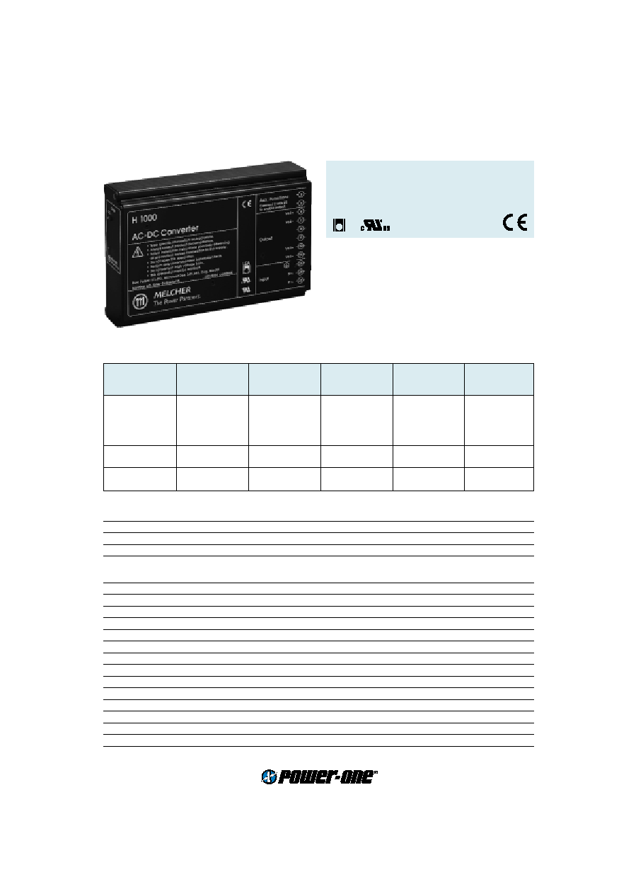
H Series
50 Watt AC-DC Converters
Input voltage range 85...255 V AC
1, 2 or 3 isolated outputs up to 48 V DC
4 kV AC I/O electric strength test voltage
Input
Input voltage
continuous range
85...255 V AC
Input frequency
47...63 Hz
Inrush current limitation
by thermistor
Output
Efficiency
U
i nom
,
I
o nom
up to 83 %
Output voltage 1 setting acc.
U
i nom
,
I
o nom
±
2%
U
o1 nom
Output voltage 2, 3 setting acc.
U
i nom
,
I
o nom
±
5 %
U
o2,3 nom
Output voltage switching noise
IEC/EN 61204, total
typ. 200 mV
pp
Line regulation
U
i min
...
U
i max
,
I
o nom
typ.
±
1%
U
o nom
Load regulation output 1
U
i nom
, 0...
I
o1 nom
typ. 0.2 %
U
o1 nom
Load regulation output 2, 3
10...100%
I
o2,3 nom
typ. 0.7 V
Output voltage 2, 3
U
i nom
,
I
o1 nom
,
I
o2,3
= 0
max. 115%
U
o2,3 nom
Cross load regulation outp. 2, 3 0...100 %
I
o1 nom
typ. 0.7 V
Minimum output current
not required
0 A
Current limitation main output
rectangular U/I characteristic
typ. 110 %
I
o nom
Current limitation aux. output(s) rectangular U/I characteristic
typ. 120 %
I
o nom
Operation in parallel
by current limitation
Hold-up time
U
i
= 230 V AC,
I
o nom
typ. 70 ms
Selection chart
Output 1
Output 2
Output 3
Rated power
Type
Options
U
o nom
I
o nom
U
o nom
I
o nom
U
o nom
I
o nom
P
o tot
Input voltage
[V DC]
[A]
[V DC]
[A]
[V DC]
[A]
[W]
85...255 V AC
5.1
11
-
-
-
-
56
LH 1001-2R
D, V
12
6
-
-
-
-
72
LH 1301-2R
D
15
4.5
-
-
-
-
67
LH 1501-2R
D
24
3
-
-
-
-
72
LH 1601-2R
D
48
1.5
-
-
-
-
72
LH 1901-2R
D
12
2
12
2
-
-
48
LH 2320-2
D
15
1.7
15
1.7
-
-
51
LH 2540-2
D
5.1
5
12
0.7
12
0.7
42
LH 3020-2
D, V
5.1
5
15
0.6
15
0.6
43
LH 3040-2
D, V
LGA

2
www.power-one.com
Edition 4/04.2001
Cassette Style
H Series
Protection
Input undervoltage lockout
typ. 60 V AC
Input overvoltage lockout
typ. 280 V AC
Input transient protection
varistor
Output
no-load, overload and short circuit proof
Output overvoltage
suppressor diode in each output
typ. 150%
U
o nom
Overtemperature
switch-off with auto restart
T
C
typ. 100
∞
C
Control
Output voltage adjustment
single output types
0...110 %
U
o1 nom
Inhibit
TTL input, output(s) disabled if left open-circuit
Status indication
LEDs: OK, inhibit
Safety
Approvals
EN 60950, UL 1950, CSA C22.2 No. 950
Class of equipment
class I
Protection degree
units without options
IP 40
Electric strength test voltage
I/case
2 kV AC
I/O
4 kV AC
O/case
1 kV AC
O/O
0.2 kV AC
EMC
Electrostatic discharge
IEC/EN 61000-4-2, contact discharge, level 2 (4 kV)
criterion A
Electromagnetic field
IEC/EN 61000-4-3, level x (20 V/m)
criterion A
Electr. fast transients/bursts
IEC/EN 61000-4-4, input, level 1 (0.5 kV)
criterion A
Surge
IEC/EN 61000-4-5, input, level 1 (0.5 kV)
criterion A
Electromagnetic emissions
CISPR 22/EN 55022, conducted
class A
CISPR 22/EN 55022, radiated
class B
Environmental
Operating ambient temperature
U
i nom
,
I
o nom
, convection cooled
≠10...50
∞
C
Operating case temperature
T
C
U
i nom
,
I
o nom
≠10...80
∞
C
Storage temperature
non operational
≠25...100
∞
C
Damp heat
IEC/EN 60068-2-3, 93 %, 40
∞
C
21 days
Vibration, sinusoidal
IEC/EN 60068-2-6, 10...60/60...150 Hz
0.15 mm/2 g
n
Shock
IEC/EN 60068-2-27, 6 ms
15 g
n
Bump
IEC/EN 60068-2-29, 16 ms
10 g
n
MTBF
MIL-HDBK-217E, G
B
, 40
∞
C, single output types
384'000 h
Options
Input and/or output undervoltage monitoring, excludes option V
D1...D8
Input and/or output undervoltage monitoring (VME), excludes option D
V2, V3

4
www.power-one.com
Edition 4/04.2001
Cassette Style
H Series
Pin allocation
Pin
Electrical Determination
LH1000
LH2000
LH3000
2
Inhibit control input
i
i
i
5
Safe Data or ACFAIL
D or V
D or V
D or V
8
Output voltage (positive)
Vo1+
Vo3+
11
Output voltage (negative)
Vo1≠
Vo3≠
14
Control input +
R
17
Control input ≠
G
14
Output voltage (positive)
Vo2+
Vo2+
17
Output voltage (negative)
Vo2≠
Vo2≠
20
Output voltage (positive)
Vo1+
Vo1+
Vo1+
23
Output voltage (negative)
Vo1≠
Vo1≠
Vo1≠
26
Protective earth
29
AC input voltage
N
N
N
32
AC input voltage
P
P
P
Accessories
Front panels 19" (Schroff/Intermas)
Mating H11 connectors with screw, solder, fast-on or press-fit terminals
Connector retention facilities and code key system for connector coding
Flexible PCB for connecting the converter via an H11 connector, if mounted on a PCB
Chassis or wall mounting plates for frontal access
Universal mounting brackets for chassis or DIN-rail mounting
2/12.2000
