1
www.power-one.com
Edition 4/04.2001
∑ Rugged electrical and mechanical design
∑ Integrated power factor correction
∑ Operating ambient temperature range
≠40...71
∞
C with convection cooling
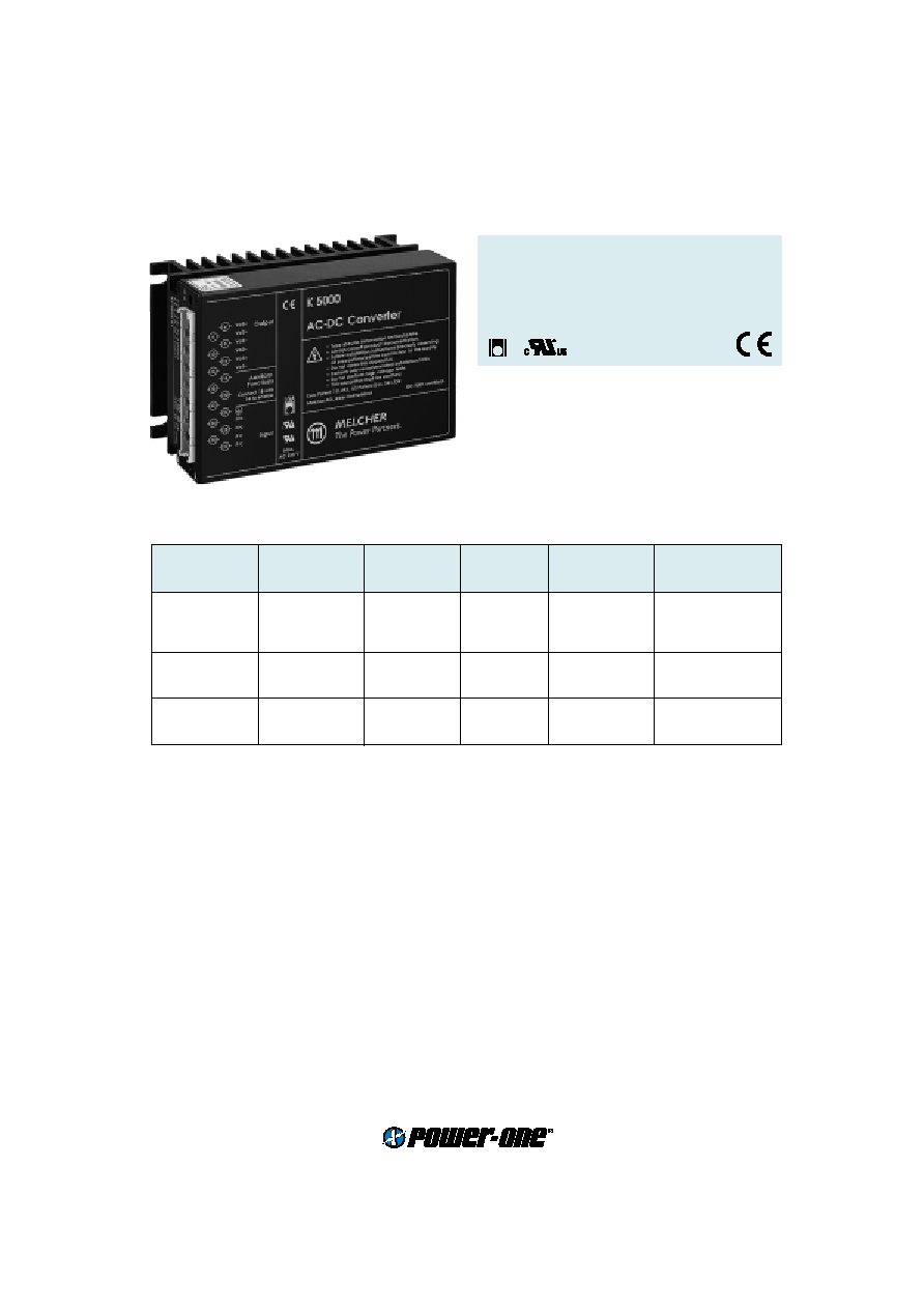
K Series with PFC
150 Watt AC-DC Converters
Input voltage range from 85...255 V AC
1or 2 isolated outputs up to 48 V DC
4 kV AC I/O electric strength test voltage
LGA
Selection chart
Output 1
Output 2
Input voltage
Efficiency
Type
Options
U
o nom
I
o nom
U
o nom
I
o nom
U
i
h
min
[V DC]
[A]
[V DC]
[A]
[V AC]
[%]
5.1
25
-
-
85...255
78
LK 4003-6R
-9, E, D, V, P, T, B1
12
12
-
-
85...255
85
LK 4301-7R
-9, E, D, P, T, B1
15
10
-
-
85...255
85
LK 4501-7R
-9, E, D, P, T, B1
24
6
-
-
85...255
86
LK 4601-7R
-9, E, D, P, T, B1
24
6
-
-
85...255
83
LK 5320-7R
-9, E, D, P, T, B1
30
5
-
-
85...255
83
LK 5540-7R
-9, E, D, P, T, B1
48
3
-
-
85...255
84
LK 5660-7R
-9, E, D, P, T, B1
12
6
12
6
85...255
83
LK 5320-7R
-9, E, D, P, T, B1
15
5
15
5
85...255
83
LK 5540-7R
-9, E, D, P, T, B1
24
3
24
3
85...255
84
LK 5660-7R
-9, E, D, P, T, B1

2
www.power-one.com
Edition 4/04.2001
Input
Input voltage AC
wide input range
85...255 V AC
Input frequency
50/60 Hz
Power factor
per IEC/EN 61000-3-2
>95%
Inrush current limitation
by thermistor
Output
Efficiency
U
i nom
,
I
o nom
up to 86 %
Output voltage setting accuracy
U
i nom
,
I
o nom
±
0.6 %
U
o nom
Output voltage switching noise
IEC/EN 61204, total
typ. 100 mV
pp
Line regulation
U
i min
...
U
i max
,
I
o nom
typ.
±
0.1 %
Load regulation
U
i nom
, 0.1...
I
o nom,
symmetrical output load
typ. 0.4 %
Minimum load
not required
0 A
Current limitation
rectangular U/I characteristic
typ. 110...100 %
I
o nom
Operation in parallel
by current limitation
Hold-up time
U
i nom
,
I
o nom
20 ms
Control and protection
Input fuse
not user accessible
4 AT
Input undervoltage lockout
typ. 80 %
U
i min
Input overvoltage lockout
typ. 115 %
U
i max
Input transient protection
varistor
Output
no-load, overload and short circuit proof
Output overvoltage
suppressor diode in each output
typ. 130%
U
o nom
Overtemperature
switch-off with auto restart
T
C
typ. 100
∞
C
Output voltage adjustment
0...110%
U
o nom
Inhibit
TTL input, output(s) disabled if open circuit
Status indication
LEDs: OK, inhibit, overload
Safety
Approvals
EN 60950, UL 1950, CSA 22.2 No. 950
Class of equipment
class I
Protection degree
IP 30
Electric strength test voltage
I/case
2 kV AC
I/O
4 kV AC
O/case
1 kV AC
O/O
0.1 kV AC
EMC
Electrostatic discharge
IEC/EN 61000-4-2, level 4 (8/15 kV)
criterion A
Electromagnetic field
IEC/EN 61000-4-3, level 3 (10 V/m)
criterion A
Electr. fast transients/bursts
IEC/EN 61000-4-4, level 4 (2/4 kV)
criterion A
Surge
IEC/EN 61000-4-5, level 3 (2 kV)
criterion A
Conducted disturbances
IEC/EN 61000-4-6, level 3 (10 V)
criterion A
Electromagnetic emissions
CISPR 22/EN 55022
class B
Cassette Style
K Series with PFC
3
www.power-one.com
Edition 4/04.2001
Environmental
Operating ambient temperature
U
i nom
,
I
o nom
, convection cooled
≠25...71
∞
C
Operating case temperature
T
C
U
i nom
,
I
o nom
≠25...95
∞
C
Storage temperature
non operational
≠40...100
∞
C
Damp heat
IEC/EN 60068-2-3, 93 %, 40
∞
C
56 days
Vibration, sinusoidal
IEC/EN 60068-2-6, 10...60/60...2000 Hz
0.35 mm/5 g
n
Shock
IEC/EN 60068-2-27, 6 ms
100 g
n
Bump
IEC/EN 60068-2-29, 6 ms
40 g
n
Random vibration
IEC/EN 60068-2-64, 20...500 Hz
4.9 g
n rms
MTBF
MIL-HDBK-217F, G
B
, 40
∞
C
514'000 h
Options
Extended temperature range
≠40...71
∞
C, ambient, operating
-9
Electronic inrush current limitation
E
Output voltage adjustment
40...100 %
U
o nom
, excludes feature R and vice versa
P
Input and/or output undervoltage monitoring, excludes option V
D0...D9
Input and/or output undervoltage monitoring (VME), excludes option D
V0, V2, V3
Current sharing
T
Cooling plate
B1
K Series with PFC
150 Watt AC-DC Converters
32 28 24 20 16 12
8
4
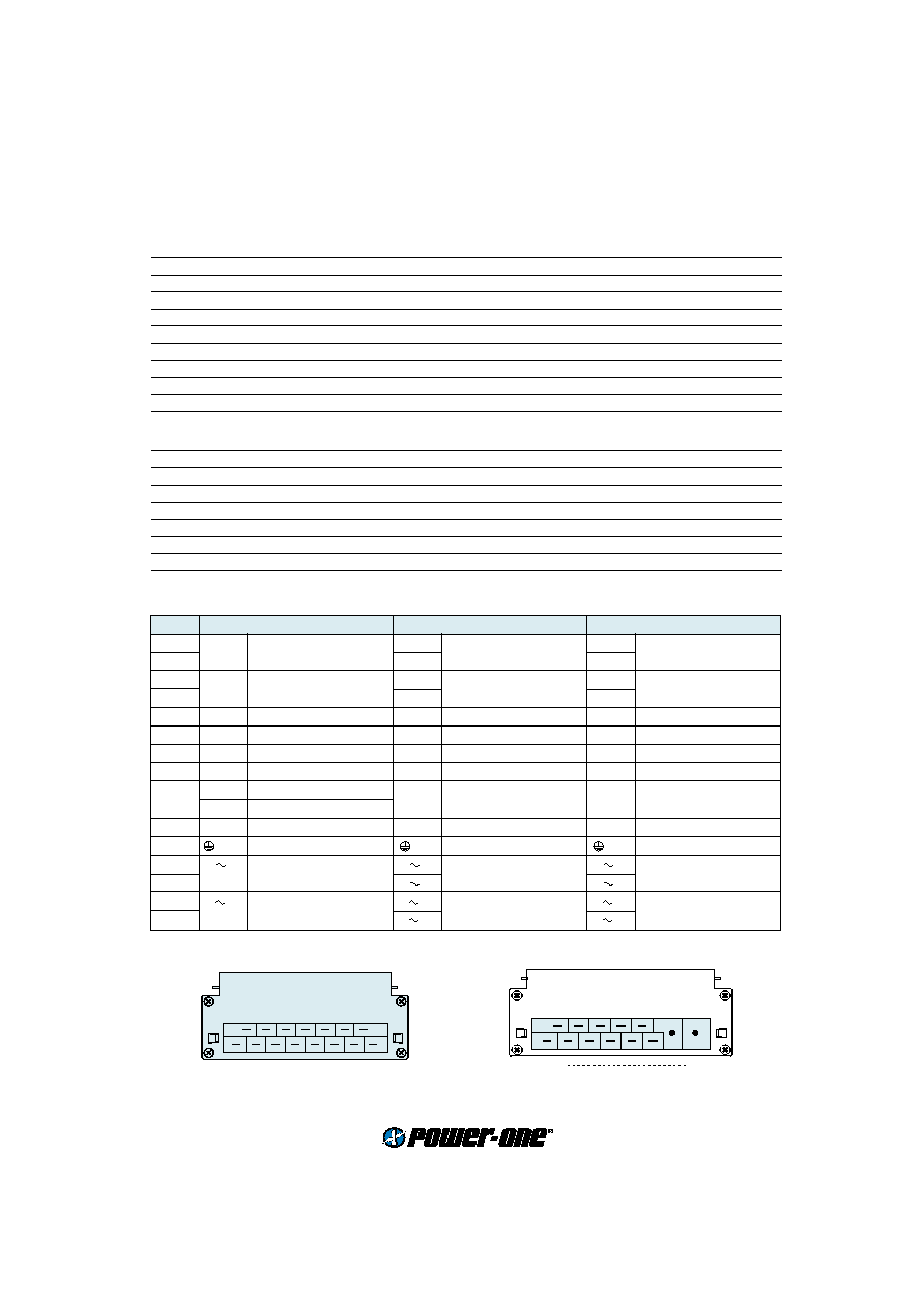
Connector type H15
S10010
30 26 22 18 14 10
6
Pin allocation
Pin
LK 4003
LK 4301, LK 4501, LK 4601
LK 5000
4
Vo1+
Output 1
Vo1+
Output 1
Vo2+
Output 2
6
Vo1+
Vo2+
8
Vo1≠
Output 1
Vo1≠
Output 1
Vo2≠
Output 2
10
Vo1≠
Vo2≠
12
S+
Sense
S+
Sense
Vo1+
Output 1
14
S≠
Sense
S≠
Sense
Vo1≠
Output 1
16
R
Control of
U
o1
R
Control of
U
o1
R
Control of
U
o1
18
i
Inhibit
i
Inhibit
i
Inhibit
20
D
Save data
D
Save data
D
Save data
V
ACFAIL
22
T
Current sharing
T
Current sharing
T
Current sharing
24
Protective earth
Protective earth
Protective earth
26
N
Input
N
Input
N
Input or Neutral
28
N
N
30
P
Input
P
Input
P
Input or Phase
32
P
P
4/6
30/32
Type H15 S2
10001
4
www.power-one.com
Edition 4/04.2001
Cassette Style
K Series with PFC
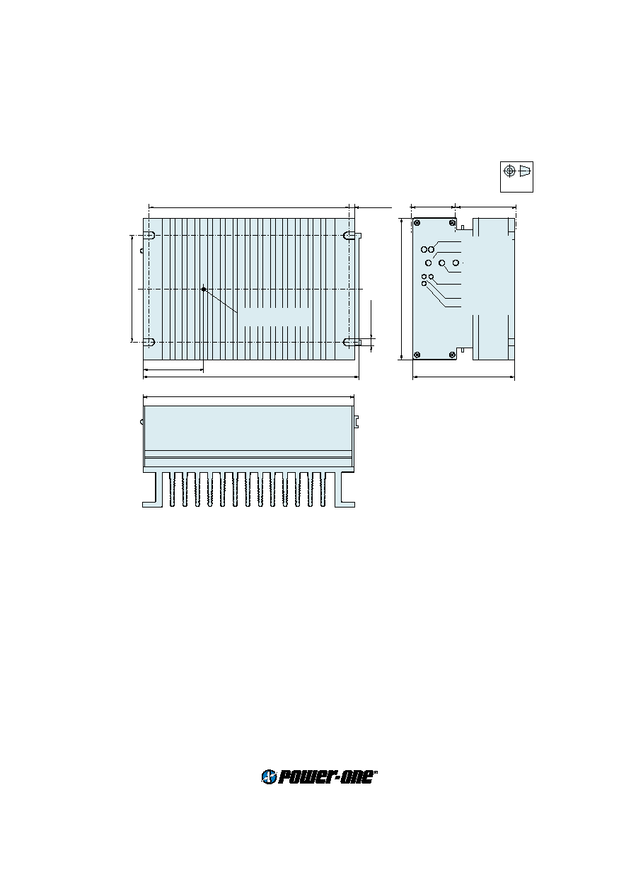
Mechanical data
Tolerances
±
0.3 mm (0.012") unless otherwise indicated.
European
Projection
Accessories
Front panels 19" (Schroff/Intermas)
Mating H15/H15S4 connectors with screw, solder, fast-on or press-fit terminals
Connector retention facilities and code key system for connector coding
Chassis or wall mounting plates for frontal access
Universal mounting brackets for chassis or DIN-rail mounting
159 (6.25")
4.5 (0.18")
89 (3.50")
111 (3U) (4.37")
168.5 (6.63")
80 (3.15")
6.5 (0.26")
7 TE
9 TE
Measuring point of
case temperature
T
C
171.93 (6.77") (DIN 41494)
50 (1.97")
S09002
Test jacks
Option P (Uo)
Option D (Uti)
LED OK
LED i
LED IoL
Option D (Uto)