1
www.power-one.com
Edition 4/04.2001
∑ Extremely slim case (4TE), fully enclosed
∑ Single outputs for 72 and 85 V DC loads
∑ Ideal to supply isolated P series DC-DC
converters
∑ Operating ambient temperature range
≠40...71
∞
C with convection cooling
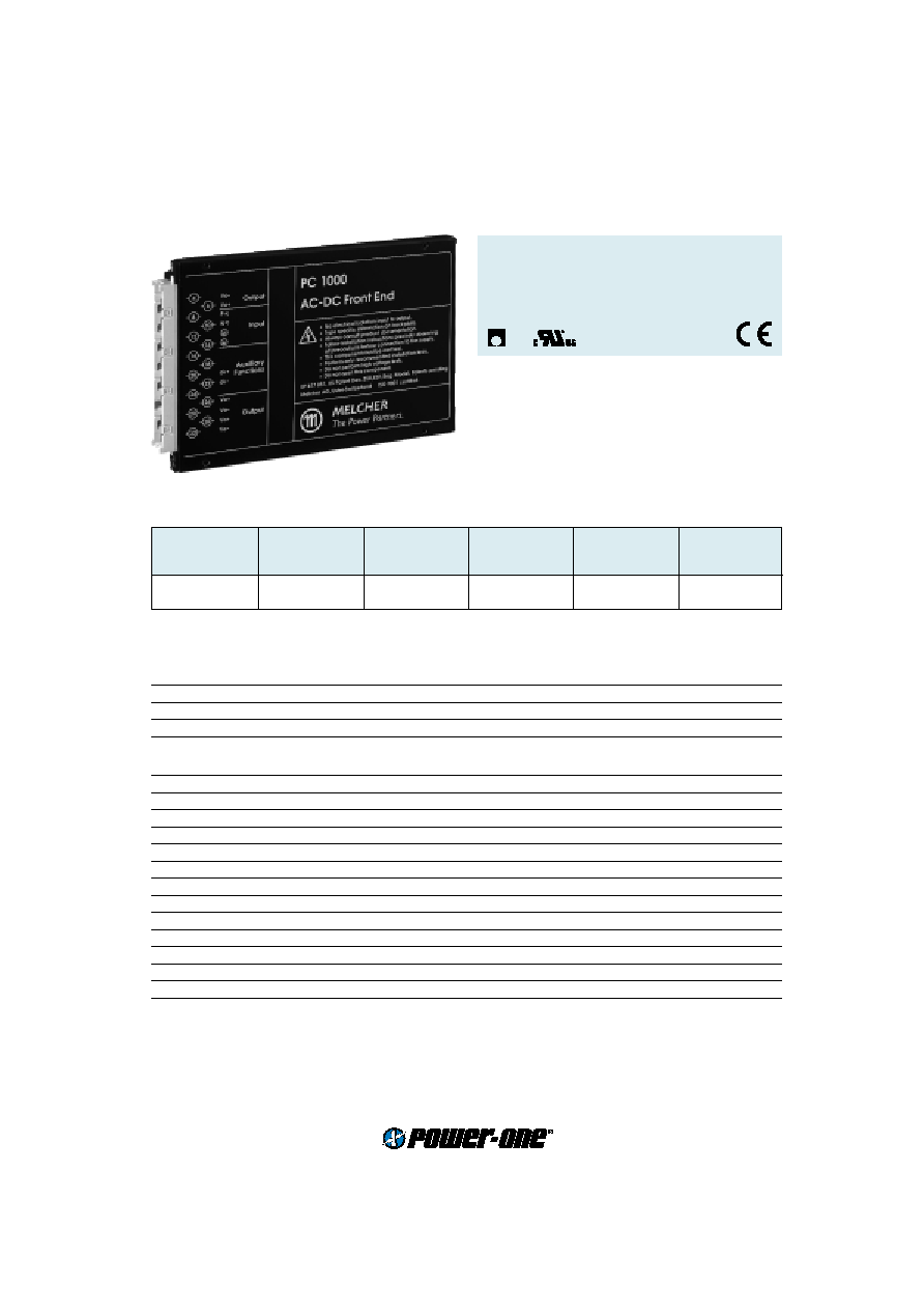
PC Series
190...230 Watt AC-DC Converters
Converter with single stage AC to DC conver-
sion and PFC
No electrical isolation input to output
Input voltage range 85(95)...255 V AC
Input
Input voltage
continuous range
85(95)...255 V AC
Input frequency
47...63 Hz
Inrush current
extremely low input capacitance of 1.25
µ
F
negligible
Output
Efficiency
U
i nom
,
I
o nom
94 %
Output voltage setting accuracy
U
i nom
,
I
o nom
±
2 V
U
o nom
Output voltage noise
IEC/EN 61204, low frequency
typ. 5 V
pp
IEC/EN 61204, switching frequency
typ. 25 mV
pp
Line regulation
U
i min
...
U
i max
,
I
o nom
typ.
±
1 V
Load regulation
U
i nom
, 10...100%
I
o nom
typ. 250 mV
U
i nom
, 0...10%
I
o nom
typ. 700 mV
Minimum output current
not required
0 A
Power limitation
approx. 1 s, restart after 3 s
typ. 240 W
Current limitation
approx. 1 s, restart after 3 s
typ. 200 %
I
o nom
Operation in parallel
by load regulation
up to 5 units
Hold-up time
U
o
= 72...66 V DC,
P
o
= 190 W
typ. 4.3 ms
U
o
= 85...40 V DC,
P
o
= 230 W
typ. 24 ms
Selection chart
Output 1
Input voltage
Rated power
Efficiency
Type
Options
U
o nom
I
o nom
U
i
P
o max
h
[V DC]
[A]
[V AC]
[W]
[%]
72
2.7
85...255
190
94
LPC 1901-7D
-9
85
2.7
95...255
230
94
LPC 1902-7D
-9
LGA

2
www.power-one.com
Edition 4/04.2001
Cassette Style
PC Series
Protection
Input undervoltage lockout
typ. 68 V AC
Input overvoltage lockout
typ. 306 V AC
Input transient protection
two varistors
Output
no-load, overload and short circuit proof
Output overvoltage
suppressor diode in each output
typ. 150%
U
o nom
Overtemperature
switch-off with auto restart
T
C
typ. 110
∞
C
Control
Status indication
LED: OK
Isolated open collector signal
In OK/Out OK
feature D
Safety
Approvals
EN 60950, UL 1950, CSA C22.2 No. 950
Class of equipment
class I
Protection degree
IP 40
Electric strength test voltage
I/case and O/case
1.5 kV AC
EMC
Electrostatic discharge
IEC/EN 61000-4-2, contact/air, level 2/3 (4/8 kV)
criterion B
Electromagnetic field
IEC/EN 61000-4-3, level 2 (3 V/m)
criterion A
Electr. fast transients/bursts
IEC/EN 61000-4-4, level 3 (2 kV)
criterion B
Surge
IEC/EN 61000-4-5, input, level 2/3 (1/2 kV)
criterion B
Conducted disturbances
IEC/EN 61000-4-6, level 2 (3 V)
criterion A
Electromagnetic emissions
CISPR 22/EN 55022, conducted
class B
CISPR 14/EN 55014, radiated
below limit
Environmental
Operating ambient temperature
U
i nom
,
I
o nom
, convection cooled
≠25...71
∞
C
Operating case temperature
T
C
U
i nom
,
I
o nom
≠25...95
∞
C
Storage temperature
non operational
≠40...100
∞
C
Damp heat
IEC/EN 60068-2-3, 93 %, 40
∞
C
56 days
Vibration, sinusoidal
IEC/EN 60068-2-6, 10...60/60...150 Hz
0.35 mm/5 g
n
Shock
IEC/EN 60068-2-27, 11 ms
50 g
n
Bump
IEC/EN 60068-2-29, 11 ms
25 g
n
Random vibration
IEC/EN 60068-2-64, 20...500 Hz
4.9 g
n rms
MTBF
MIL-HDBK-217E, G
B
, 40
∞
C, notice 2
763'000 h
Options
Extended temperature range
≠40...71
∞
C, ambient, operating
-9
3
www.power-one.com
Edition 4/04.2001
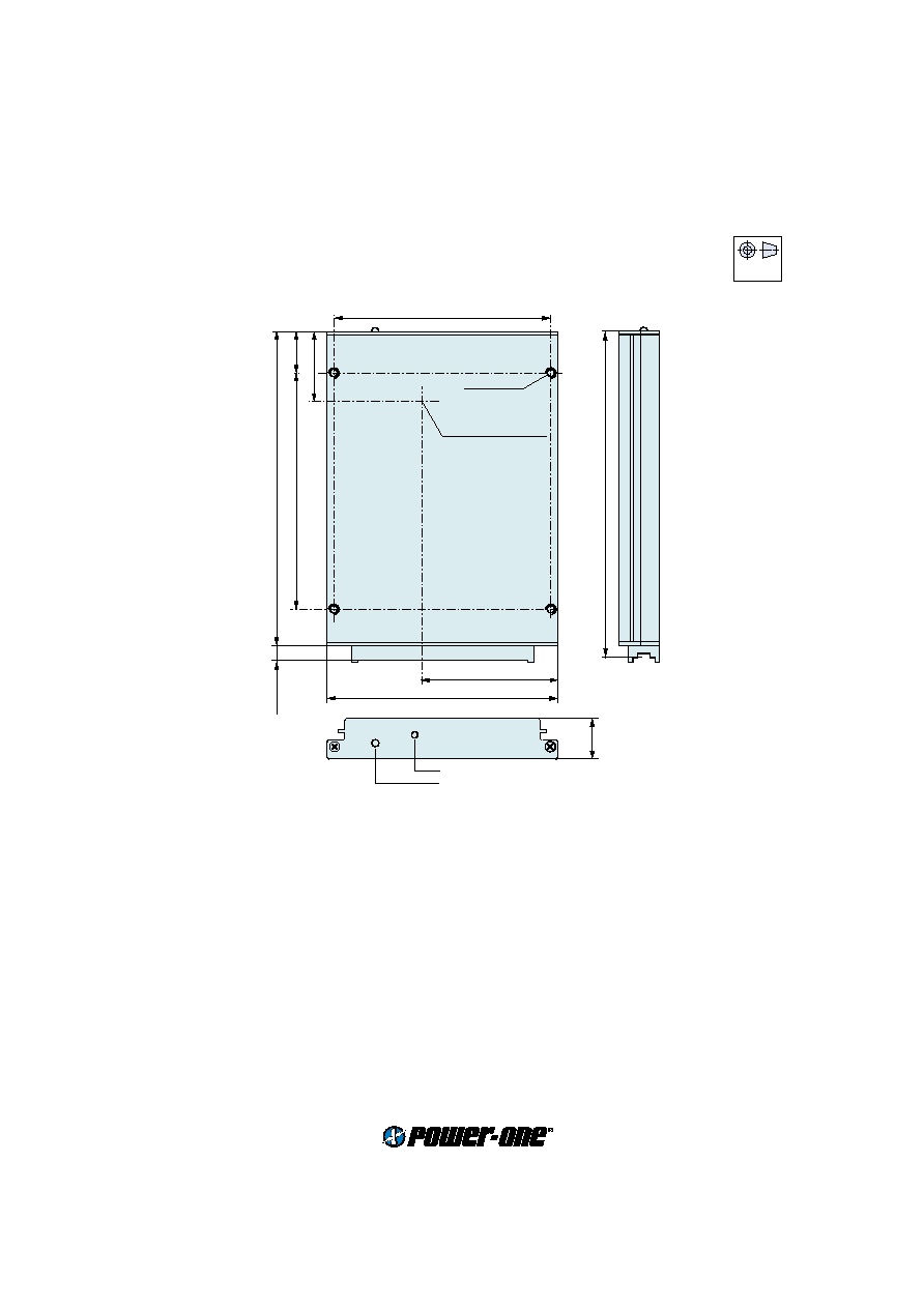
Mechanical data
Tolerances
±
0.3 mm (0.012") unless otherwise indicated.
PC Series
190...230 Watt AC-DC Converters
European
Projection
104 (4.09")
65 (2.56")
111 (4.37")
20 (0.79")
127 (5.18")
164 (6.46")
8 (0.31")
19.8
(0.78")
Potentiometer (option P)
LED "OUT OK"
171.93 (DIN 41494) (6.76")
S09106
M3, 4 deep
Measuring point of
case temperature
T
C
35 (1.38")