
Product Specifications
NV Series: 4 - 6W DC/DC Converters
Oct 2001
9-36V, 18-36V, 36-72V & 16-75V Inputs
3.3V, 5.0V, 12V, 15V, ±5.0V, ±12V, ±15V & ±24V Outputs
18-Oct-01
Rev 1.0
Page
1 of 11
www.power-one.com
Applications
∑
Distributed power architectures
∑
Telecommunications equipment
∑
LAN/WAN applications
∑
Data processing
Features
∑
Single board design
∑
8.5 mm height profile
∑
Excellent co-planarity
∑
Input/output isolation: 1500 Vdc
∑
Low conducted and radiated EMI
∑
Output overcurrent protection
∑
Parallel and series connection providing
flexible output voltages and power
∑
Full rated output power at 71∫C with
convection cooling
∑
Operating temperature to 110∫C
∑
UL, CSA and EN/IEC60950 (3
rd
ed.) approved
Description
The NV series of converters are low profile, single and dual outputs, DC/DC converters intended for SMT
placement and reflow soldering. The product provides on-board conversion of a wide range of standard
telecom and datacom input voltages to isolated low output voltages. Proprietary patented manufacturing
process with full process automation ensures optimal product quality in an extremely small footprint.
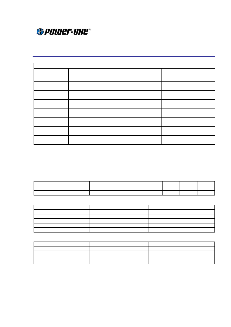
Selection Chart ≠ Single output
Model
Input
voltage,
Vdc
Input
current,
max, Adc
Output
voltage,
Vdc (Vo)
Output rated
current,
Adc (Io.Max)
Output ripple
and noise,
mVp-p
Efficiency,
%
NVS01YG -M6
18-36
0.27
5.0
1.0
50
82
NVS0.5YH-M6
18-36
0.33
12
0.5
95
83
NVS0.4YJ-M6
18-36
0.33
15
0.4
120
84
NVS01ZE-M6
36-75
0.17
5.0
1.0
50
82
NVS0.5ZH-M6
36-75
0.17
12
0.5
95
82
NVS0.4ZJ-M6
36-75
0.17
15
0.4
120
84
NVS0.9CE-M6
9-36
0.45
3.3
0.9
50
79
NVS0.7CG-M6
9-36
0.55
5.0
0.7
50
81
NVS0.3CH-M6
9-36
0.65
12
0.34
95
82
NVS0.3CJ-M6
9-36
0.65
15
0.28
120
82
NVS0.9EE-M6
18-75
0.33
3.3
0.9
50
80
NVS0.7EG-M6
18-75
0.33
5.0
0.7
50
81
NVS0.3EH-M6
18-75
0.33
12
0.34
95
82
NVS0.3EJ-M6
18-75
0.33
15
0.28
120
82
Continued next page
Product Specifications
NV Series: 4 - 6W DC/DC Converters
Oct 2001
9-36V, 18-36V, 36-72V & 16-75V Inputs
3.3V, 5.0V, 12V, 15V, ±5.0V, ±12V, ±15V & ±24V Outputs
18-Oct-01
Rev 1.0
Page
2 of 11
www.power-one.com
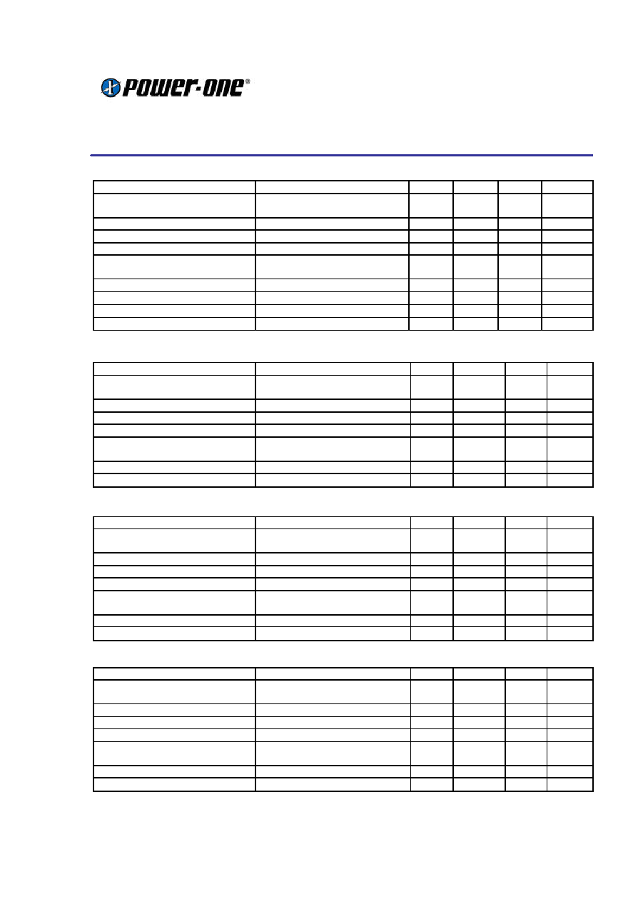
Continued from previous page
Selection Chart ≠ Dual Outputs
Model
Input
voltage,
Vdc
Input
current,
max, Adc
Output
voltage,
Vdc (Vo)
Output rated
current,
Adc (Io.Max)
Output ripple
and noise,
mVp-p
Efficiency,
%
NVD01YGG-M6
18-36
0.27
±5.0
±0.50
60
82
NVD0.5YHH-M6
18-36
0.33
±12
±0.25
100
83
NVD0.3YJJ-M6
18-36
0.33
±15
±0.14
120
84
NVD01ZGG-M6
36-75
0.17
±5.0
±0.50
60
82
NVD0.5ZHH-M6
36-75
0.17
±12
±0.25
100
83
NVD0.3ZJJ-M6
36-75
0.17
±15
±0.14
120
84
NVD0.7CGG-M6
9-36
0.65
±5.0
±0.35
50
81
NVD0.3CHH-M6
9-36
0.65
±12
±0.17
95
82
NVD0.3CJJ-M6
9-36
0.65
±15
±0.14
120
82
NVD0.1CKK-M6
9-36
0.65
±24
±0.08
190
83
NVD0.7EGG-M6
18-75
0.33
±5.0
±0.35
50
81
NVD0.3EHH-M6
18-75
0.33
±12
±0.17
95
82
NVD0.3EJJ-M6
18-75
0.33
±15
±0.14
120
82
NVD0.1E KK-M6
18-75
0.33
±24
±0.08
190
83
Absolute Maximum Ratings
Stresses in excess of the absolute maximum ratings may cause performance degradation, adversely affect
long term reliability and cause permanent damage to the converter. Specifications apply over specified input
voltage, output load and temperature range, unless otherwise noted.
Parameter
Conditions/Description
Min
Max
Units
Operating CaseTemp. (Tc)
At 100% load
-40
110
∞
C
Storage Temperature (Ts)
-55
120
∞
C
Environmental and Mechanical Specifications
Parameter
Conditions/Description
Min
Nom
Max
Units
Shock
IEC68-2-27
100
g
Sinusoidal Vibration
IEC68-2-6
10
g
Weight
0.4/12
oz/g
Water Washing
Standard process
Yes
N/A
MTBF
Per Bellcore TR-NWT-000332
3,000
kHrs
Isolation Specifications
Parameter
Conditions/Description
Min
Nom
Max
Units
Insulation Safety Rating
Vin = Vin.Min ≠ Vin.Max
Operational
N/A
Isolation Voltage (Vps)
1,500
Vdc
Isolation Resistance (Rps)
10
MOhm
Isolation Capacitance (Cps)
1,100
pF
Product Specifications
NV Series: 4 - 6W DC/DC Converters
Oct 2001
9-36V, 18-36V, 36-72V & 16-75V Inputs
3.3V, 5.0V, 12V, 15V, ±5.0V, ±12V, ±15V & ±24V Outputs
18-Oct-01
Rev 1.0
Page
3 of 11
www.power-one.com
Input Specifications (9-36V)
Parameter
Conditions/Description
Min
Nom
Max
Units
Input voltage (Vin)
Transient Input Voltage (Vint)
Continuous
Transient, 100ms
9
36
40
Vdc
Vdc
Input Current when Shutdown
Vin.Nom, Iout = 0A
10
20
mAdc
Turn-On Input Voltage 9-36 Vin
Ramping Up, Io.Max
8
8.5
9
Vdc
Turn-Off Input Voltage 9-36 Vin
Ramping Down, Io.Max
8
8.5
9
Vdc
Turn-On Time
To Output Regulation Band
Rise Time
250
10
500
ms
ms
Input Reflected Ripple Current
Vin.Max, Io.Max
30
mAp-p
Input Capacitance
0.6
µ
F
Switching Frequency
Vin.Nom, Io.Max
250
kHz
Temperature Coefficient
0.02
%Vo/
∞
C
Input Specifications (18-36V)
Parameter
Conditions/Description
Min
Nom
Max
Units
Input voltage (Vin)
Transient Input Voltage (Vint)
Continuous
Transient, 100ms
18
36
40
Vdc
Vdc
Input Current when Shutdown
Vin.Nom, Iout = 0A
10
20
mAdc
Turn-On Input Voltage 9-36 Vin
Ramping Up, Io.Max
16
17
18
Vdc
Turn-Off Input Voltage 9-36 Vin
Ramping Down, Io.Max
16
17
18
Vdc
Turn-On Time
To Output Regulation Band
Rise Time
250
10
500
ms
ms
Input Reflected Ripple Current
Vin.Max, Io.Max
30
mAp-p
Input Capacitance
0.6
µ
F
Input Specifications (16-75V)
Parameter
Conditions/Description
Min
Nom
Max
Units
Input voltage (Vin)
Transient Input Voltage (Vint)
Continuous
Transient, 100ms
16
75
100
Vdc
Vdc
Input Current when Shutdown
Vin.Nom, Iout = 0A
8
10
mAdc
Turn-On Input Voltage 9-36 Vin
Ramping Up, Io.Max
14
15
16
Vdc
Turn-Off Input Voltage 9-36 Vin
Ramping Down, Io.Max
14
15
16
Vdc
Turn-On Time
To Output Regulation Band
Rise Time
250
10
500
ms
ms
Input Reflected Ripple Current
Vin.Max, Io.Max
30
mAp-p
Input Capacitance
0.3
µ
F
Input Specifications (36-75V)
Parameter
Conditions/Description
Min
Nom
Max
Units
Input voltage (Vin)
Transient Input Voltage (Vint)
Continuous
Transient, 100ms
36
75
100
Vdc
Vdc
Input Current when Shutdown
Vin.Nom, Iout = 0A
8
10
mAdc
Turn-On Input Voltage 9-36 Vin
Ramping Up, Io.Max
32
34
36
Vdc
Turn-Off Input Voltage 9-36 Vin
Ramping Down, Io.Max
32
34
36
Vdc
Turn-On Time
To Output Regulation Band
Rise Time
250
10
500
ms
ms
Input Reflected Ripple Current
Vin.Max, Io.Max
30
mAp-p
Input Capacitance
0.3
µ
F
Product Specifications
NV Series: 4 - 6W DC/DC Converters
Oct 2001
9-36V, 18-36V, 36-72V & 16-75V Inputs
3.3V, 5.0V, 12V, 15V, ±5.0V, ±12V, ±15V & ±24V Outputs
18-Oct-01
Rev 1.0
Page
4 of 11
www.power-one.com
Output Specifications
All specifications apply over input voltage, output load and temperature range, unless otherwise noted.
All Models
Parameter
Conditions/Description
Min
Nom
Max
Units
Output Voltage Accuracy
Vin.Nom, 50% Io.Max
±1
%Vo
Line Regulation
Vin.Min to Vin.Max, 50% Io.Max
±1
%Vo
Load Regulation
Vin.Nom, Io.Min to Io.Max
3.3Vo
Other Output Voltages
±3.5
±3.0
%Vo
%Vo
Maximum Output Capacitance
Total, for single and dual outputs
3.3Vo
5Vo, ±5Vo
12Vo, ±12Vo
15Vo, ±12Vo
±24Vo
680
680
150
100
45
µ
F
µ
F
µ
F
µ
F
µ
F
Dynamic Regulation
Peak Deviation
Settling Time
50-100% Io.Max load step
change
to 1% error band
5.0
1.0
%Vo
ms
Output Voltage Ripple
Vin.Min to Vin.Max, Io.Min to Io
Max, 20MHz Bandwidth
3.3Vo
5Vo, ±5Vo
12Vo, ±12Vo, ±24Vo
50
50
0.8
80
80
1
mVp-p
mVp-p
%Vo p-p
Output Current Limit Threshold
Output Current Limit Threshold
120
200
%Io.Max
Switching Frequency
Vin.Nom, Io.Max
250
KHz
Temperature Coefficient
0.02
%Vo/
∞
C
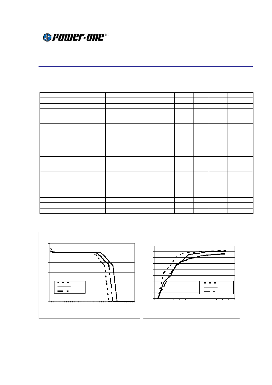
Typical characteristic curves for single 5V output type
Output Voltage Vs Load
0.00
1.00
2.00
3.00
4.00
5.00
6.00
0.00
0.18
0.36
0.54
0.72
0.90
1.08
1.26
1.44
1.62
1.80
1.98
2.16
2.34
Iout (A)
Vout (V)
Vin Min
Vin Nom
Vin Max
Efficiency Vs Load
0%
10%
20%
30%
40%
50%
60%
70%
80%
90%
0%
6%
12%
24%
36%
48%
60%
72%
84%
96%
108%
120%
Iout (A)
Efficiency
Vin Min
Vin Nom
Vin Max
25% 50% 75% 100%

Product Specifications
NV Series: 4 - 6W DC/DC Converters
Oct 2001
9-36V, 18-36V, 36-72V & 16-75V Inputs
3.3V, 5.0V, 12V, 15V, ±5.0V, ±12V, ±15V & ±24V Outputs
18-Oct-01
Rev 1.0
Page
5 of 11
www.power-one.com
Temperature Derating Curves
The derating curves below give an indication of
the output power achievable with and without
forced air-cooling. However in the final application
the temperature rise of the converter is also
influenced by factors such as heat conduction
through the leads to the PCB, orientation, the
temperature of surrounding components and the
input voltage. To ensure the reliability of the
converter, care must be taken to guarantee that
the maximum case temperature is not exceeded
under any conditions. The measurement point for
case temperature is specified on the mechanical
drawing (Tc).
Temperature derating for 18-36V and 36-75V
input voltage ranges :
The 9-36V and 18-75V input voltage versions of
this series feature a 4:1 input voltage range and
can achieve operation at full power at 85∫C
ambient temperature with only convection cooling.
Temperature derating for 9-36V and 18-75V input
voltage ranges :
Typical Application
This series of converters does not require any
external components for proper operation.
However, if the distribution of the input voltage to
the converter contains significant inductance, a
capacitor across the input terminals may be
required to stabilize the input voltage. A minimum
of 0.47µF, quality electrolytic / ceramic capacitor
is recommended for this purpose. For output
decoupling it is recommended to connect, directly
across the output pins, a 0.47µF ceramic
capacitor (for 3.3V and 5V outputs) or a 0.27µF
ceramic capacitor (for other outputs).
Care must be taken to ensure the maximum rated
output capacitance for the device is not exceed
when dimensioning decoupling capacitors in the
system as this could cause the unit to detect an
overload and enter a `hiccup' mode of operation.
Output Power Vs Ambient Temp. & Airflow
0
20
40
60
80
100
120
0
10
20
30
40
50
60
70
80
90
100
110
Ambient Temp. (deg ∞C)
Output Power (%)
400LFM (2 m/s)
200LFM (1 m/s)
0 LFM
Output Power Vs Ambient Temp. & Airflow
0
20
40
60
80
100
120
0
15
25
35
45
55
65
75
85
95
105
110
Ambient Temp. (deg ∞C)
Output Power (%)
200LFM (1 m/s)
0 LFM