1
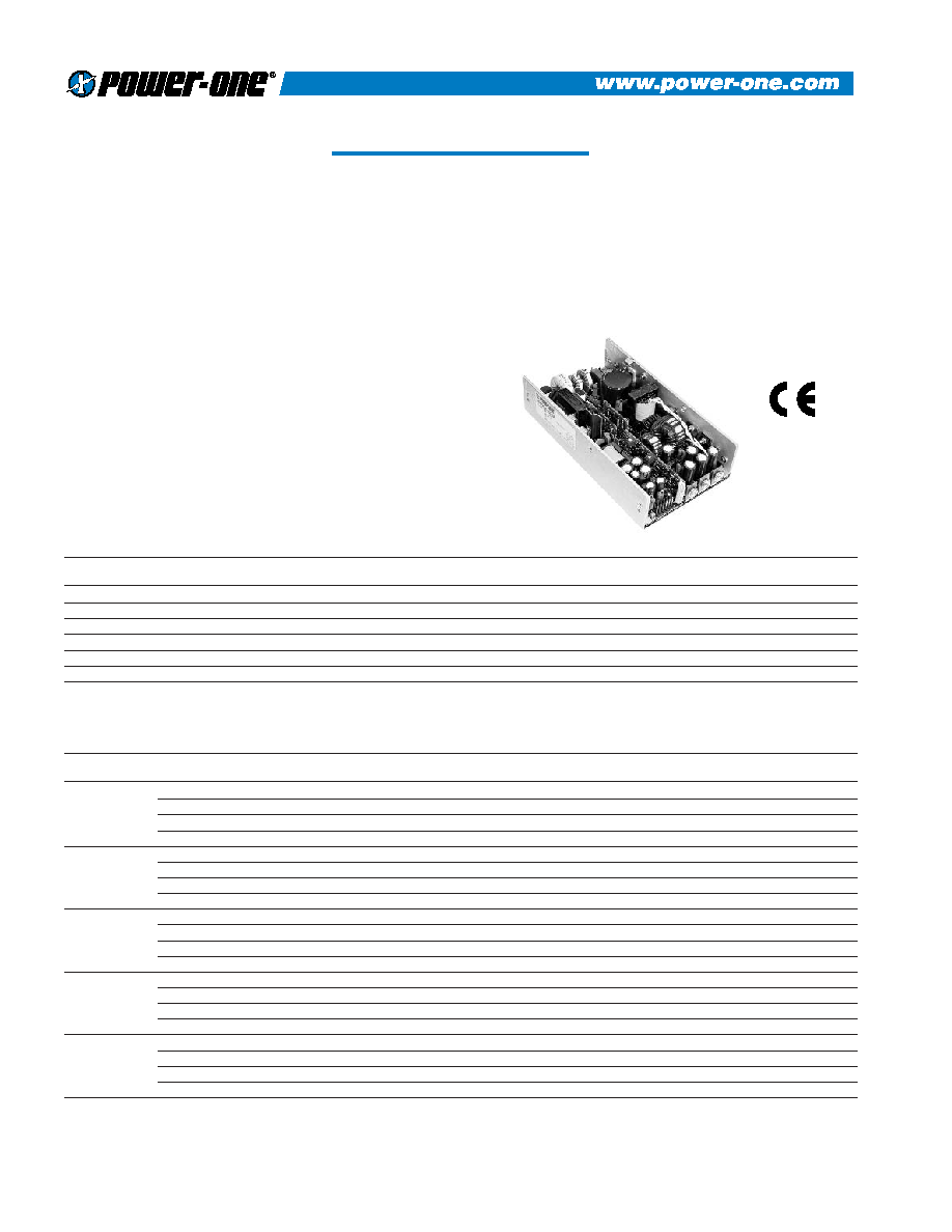
PerFormanCe POWER PFC250
The PerFormanCe Power PFC250 series combines Power Factor
Correction (PFC) with wide range outputs to meet the requirements
of data communications and industrial controls. The PFC250-4530
and PFC250-4350 provide high current +3.3V and +5V on a single
platform to support mixed mode, high-speed digital circuitry.
Power-One's unique dual converter architecture combines high
reliability with exceptional regulation.
All models feature remote sense on outputs V1 and V2 to provide
independent compensation of output cable losses. Other standard
features include independent current sharing on V1 and V2, thermal
shutdown, and remote inhibit. Airflow of 300 linear feet per minute
(LFM) is required to deliver the full power density of 3.0 watts per
cubic inch.
The PerFormanCe Power PFC250 meets international safety
requirements and is CE Marked to the Low Voltage Directive.
FEATURES
∑ Active Power Factor Correction (PFC) Meets EN61000-3-2
∑ Dual Main Outputs Provide 3.3V and 5V for Mixed Mode Applications
∑ Single Wire Current Sense on Outputs V1 and V2
∑ Remote Sense on Outputs V1 and V2
∑ Overtemperature, Overload, and Overvoltage Protection
∑ Available with Metric or SAE Mountings
∑ Isolated V3 and V4 can be Used as Positive or Negative Outputs
∑ Greater than 200,000 Hours MTBF
MULTIPLE OUTPUT MODEL SELECTION CHART ≠
250W WITH 300 LFM FORCED-AIR COOLING
ISOLATED V3 AND V4 CAN BE USED AS POSITIVE OR NEGATIVE OUTPUTS
MODEL
OUTPUT
ADJUSTMENT
OUTPUT
LINE
LOAD
RIPPLE & NOISE
INITIAL SETTING
VOLTAGE
RANGE
CURRENT
REGULATION
REGULATION
%p-p (NOTE 1)
ACCURACY
+5V
5.0V to 5.5V
40A
0.5%
1%
1%
4.98V to 5.02V
PFC250-4000
+12V
10.8V to 13.2V
10A
0.5%
1%
1%
11.94V to 12.06V
(Note 2)
12V
10.8V to 13.2V
6A
0.5%
7%
1%
11.94V to 12.06V
5V
5.0V to 5.5V
3A
0.5%
2%
1%
4.98V to 5.02V
+5V
5.0V to 5.5V
40A
0.5%
1%
1%
4.98V to 5.02V
PFC250-4001
+12V
10.8V to 13.2V
10A
0.5%
1%
1%
11.94V to 12.06V
(Note 2)
12V
10.8V to 13.2V
6A
0.5%
7%
1%
11.94V to 12.06V
12V
10.8V to 13.2V
3A
0.5%
7%
1%
11.94V to 12.06V
+5V
5.0V to 5.5V
40A
0.5%
1%
1%
4.98V to 5.02V
PFC250-4004
+12V
10.8V to 13.2V
10A
0.5%
1%
1%
11.94V to 12.06V
(Note 3)
15V
13.5V to 16.5V
6A
0.5%
7%
1%
14.92V to 15.08V
15V
13.5V to 16.5V
3A
0.5%
7%
1%
14.92V to 15.08V
+3.3V
3.15V to 3.45V
40A
0.5%
1.5%
1%
3.28V to 3.32V
PFC250-4350
+5V
5.0V to 5.5V
20A
0.5%
1%
1%
5.00V to 5.04V
(Note 2)
12V
10.8V to 13.2V
6A
0.5%
7%
1%
11.94V to 12.06V
12V
10.8V to 13.2V
3A
0.5%
7%
1%
11.94V to 12.06V
+5V
5.0V to 5.5V
40A
0.5%
1%
1%
4.98V to 5.02V
PFC250-4530
+3.3V
3.15V to 3.45V
20A
0.5%
1.5%
1%
3.28V to 3.32V
(Note 2)
12V
10.8V to 13.2V
6A
0.5%
7%
1%
11.94V to 12.06V
12V
10.8V to 13.2V
3A
0.5%
7%
1%
11.94V to 12.06V
NOTES: 1) Maximum peak-to-peak expressed as a percentage of output voltage, 20 MHz bandwidth.
2) Total current available from V1 + V2 is 40 amperes, total current available from V3 + V4 is 6.6 amperes.
3) Total current available from V1 + V2 is 40 amperes, total current available from V3 + V4 is 6.0 amperes.
SINGLE OUTPUT MODEL SELECTION CHART
MODEL
OUTPUT
ADJUSTMENT
MAXIMUM OUTPUT
LINE
LOAD
RIPPLE & NOISE
INITIAL SETTING
VOLTAGE
RANGE
CURRENT (NOTE 1)
REGULATION
REGULATION
%p-p (NOTE 2)
ACCURACY
PFC250-1003
3.3V
3.15V to 3.45V
50A
0.5%
0.8%
1%
3.28V to 3.32V
PFC250-1005
5V
4.5V to 5.5V
50A
0.5%
0.8%
1%
4.98V to 5.02V
PFC250-1012
12V
10.8V to 13.5V
23A
0.5%
0.8%
1%
11.94V to 12.06V
PFC250-1015
15V
13.5V to 18.3V
18.3A
0.2%
1.0%
1%
14.92V to 15.08V
PFC250-1024
24V
21.6V to 26.4V
10.5A
0.5%
0.8%
1%
23.88V to 24.12V
PFC250-1048
48V
46.0V to 56.0V
6A
0.5%
1.0%
1%
47.52V to 48.48V
NOTES:
1) Output currents ratings are expressed with 300 LFM forced air.
2) Maximum peak-to-peak noise expressed as a percentage of output voltage, 20 MHz bandwidth.
REV. 08/01
2
PerFormanCe POWER PFC250
INPUT SPECIFICATIONS
PARAMETER
CONDITIONS/DESCRIPTION
MIN
NOM
MAX
UNITS
Input Voltage - AC
Continuous input range.
85
264
VAC
Input Frequency
AC Input.
47
63
Hz
Brown Out Protection
Lowest AC input voltage that regulation is maintained with full rated loads.
80
VAC
Hold-up Time
After last AC line peak at 250 watts.
20
mS
Input Current
85 VAC at full rated load.
4.5
A
RMS
Input Protection
Non-user serviceable internally located AC input line fuse.
Inrush Surge Current
Internally limited by thermistor. Vin = 230 VAC, one cycle, 25∞C.
35
A
PK
Power Factor
Per EN61000-3-2.
0.95
W/VA
Operating Frequency
Switching frequency of main output transformer.
129
Switching frequency of secondary transformer.
70
kHz
Switching frequency of Power Factor Correction circuit.
60
OUTPUT SPECIFICATIONS
PARAMETER
CONDITIONS/DESCRIPTION
MIN
NOM
MAX
UNITS
Efficiency
Full rated load, 110 VAC. Varies with distribution of loads among outputs.
65
75
%
Minimum Load, V1
Minimum load required to maintain regulation on V2
Single output models
0
at maximum loading
All other models
4
Amps
Minimum Load, V3
Minimum load required to maintain regulation on V4
Single output models
N/A
at maximum loading
PFC250-4000
1.25
Amps
All other models
0.6
Ripple and Noise
Full load, 20 MHz bandwidth.
See Model Selection Charts
Output Power
300 LFM forced-air cooling.
250
Watts
Overshoot /Undershoot
Output voltage overshoot/undershoot at turn-on.
0
%
Regulation
Varies by output. Total regulation includes: line changes over the specified
See Model Selection Charts
input range, changes in load starting at 20% load and changing to 100% load.
Transient Response
Recovery time to within 1% of initial set point due to a 25% step load from any
500
S
load setting from minimum to maximum load.
Turn-on Delay
Time required for initial output voltage stabilization.
2
Sec
Turn-on Rise Time
Time required for output voltage to rise from 10% to 90%.
20
mS
INTERFACE SIGNALS AND INTERNAL PROTECTION
PARAMETER
CONDITIONS/DESCRIPTION
MIN
NOM
MAX
UNITS
Overvoltage Protection
Latch style overvoltage protection. Available on all
3.3V output, V1
4.1
4.65
single output models and V1, V2, and V3 on all multiple
3.3V output, V2
4.2
4.2
output models.
5V output, V1, V2
6.0
6.4
12V output, V1, V2
14.0
16.0
V
15V output, V1
18.3
19.8
24V output, V1
27.0
30.7
48V output, V1
60.0
70.0
Overload Protection
Fully protected against output overload and short circuit. Automatic recovery upon removal of overload condition.
Overtemperature Protection
System shutdown due to excessive internal temperature, automatic reset.
Output Good
TTL compatible signal. Signal is high when V1 output is
3.3V
3.16
V
within 5% of nominal. Signal shall remain low for 20
5V
4.75
milliseconds following loss of Output Good.
Input Power
TTL compatible logic signal. Time before regulation dropout due to loss of input
5
mS
Fail Warning
power. May be used as independent PSOK signal in redundant applications.
Current Share
Accuracy of shared current with up to 6 parallel units. Single-wire current share
10
%
on V1 and V2 with return via vegative (-) Sense return. Minimum current share load is 6A.
Remote Sense
Available on V1 and V2. Total voltage compensation for cable losses with
250
mV
respect to the main output.
Inhibit
Output voltage is inhibited by application of external high (5V) signal.
Standby Power
Available with fan option versions only (+5VDC).
100
mA
3
PerFormanCe POWER PFC250
SAFETY, REGULATORY, AND EMI SPECIFICATIONS
PARAMETER
CONDITIONS/DESCRIPTION
MIN
NOM
MAX
UNITS
Agency Approvals
UL1950.
CSA 22.2 NO. 234/950.
Approved
EN60950 (TÐV).
Dielectric Withstand Voltage
Input to Output per EN60950.
2600
VDC
Electromagnetic Interference
FCC CFR title 47 Part 15 Sub-Part B - Conducted.
B
EN55022 / CISPR 22 Conducted.
B
Class
ESD Susceptibility
Per EN61000-4-2, level 4.
8
kV
Radiated Susceptibility
Per EN61000-4-3, level 3.
10
V/M
EFT/Burst
Per EN61000-4-4, level 4.
±4
kV
Input Transient Protection
Per EN61000-4-5 level 3.
Line to Line
1
kV
Line to Ground
2
Insulation Resistance
Input to Output.
10
M
Leakage Current
Per EN60950, 264 VAC.
1500
A
ENVIRONMENTAL SPECIFICATIONS
PARAMETER
CONDITIONS/DESCRIPTION
MIN
NOM
MAX
UNITS
Altitude
Operating.
10k
ASL Ft.
Non-Operating.
40k
ASL Ft.
Operating Temperature
At 100% load:
0
50
∞C
Derate linearly above 50∞C by 2.5% per ∞C.
At 50% load:
70
∞C
Storage Temperature
-55
85
∞C
Temperature Coefficient
0∞C to 70∞C (after 15 minute warmup).
±0.02
±0.05
%/∞C
Relative Humidity
Non-Condensing.
5
95
%RH
Shock
Peak acceleration.
20
G
PK
Vibration
Random vibration, 10 Hz to 2 kHz, 3 axes.
6
G
RMS
OPTIONS
DESCRIPTION
NOTES
SIZE IMPACT
Metric Mounting
Add "M" as a suffix to the model number to order chassis with
8.50" x 4.75" x 2.00"
M4 x 0.7 mounting inserts.
(215.9mm x 120.7mm x 50.8mm)
Fan
Add "F" as a suffix to the model number to order integral fan.
10.00" x 4.75" x 2.50"
Adds 1.5" (38.1mm) to overall length and 0.5" (12.7mm) to height.
(250.4mm x 120.7mm x 63.5mm)
NUCLEAR AND MEDICAL APPLICATIONS Power-One products are not authorized for use as critical components in life support systems,
equipment used in hazardous environments, or nuclear control systems without the express written consent of the President of Power-One, Inc.
TECHNICAL REVISIONS The appearance of products, including safety agency certifications pictured on labels, may change depending on the
date manufactured. Specifications are subject to change without notice.

4
CHASSIS: 0.063" (1.6mm) ALUMINUM ALLOY,
WITH CLEAR FINISH
08
*
CONNECTOR
MOLEX
HOUSING
PIN
PINS
PINS
WIRE
SERIES
SERIES
(LOOSE)
(CHAIN)
GAUGE
41695
09-50-8051
6838
08-50-0189
08-50-0187
18-20AWG
J1
41695
09-50-8051
2478
08-50-0106
08-50-0105
18-20AWG
2139
09-50-3051
2478
08-50-0106
08-50-0105
18-20AWG
41695
09-50-8061
6838
08-50-0189
08-50-0187
18-20AWG
J3
41695
09-50-8061
2478
08-50-0106
08-50-0105
18-20AWG
2139
09-50-3061
2478
08-50-0106
08-50-0105
18-20AWG
J6
*
5264-N
50-37-5103
5263
08-70-1040
08-70-1039
22-28AWG
OVERALL SIZE: 8.50" x 4.75" x 2.00" (215.9mm x 120.7mm x 50.8mm)
OVERALL LENGTH WITH FAN: 10.00" (250.4mm)
WEIGHT: 2.75 LBS (1.25 kg)
PerFormanCe POWER PFC250
*
NOTE: THE +5V @ 100mA STANDBY POWER OUTPUT (J6-11) IS
AVAILABLE ONLY ON UNITS WITH THE FAN OPTION.