(888) IPD-CONVerters
q
(888) 473-2668
q
www.ipdconverters.com
1
Turn-On Time
30 ms
Remote Shutdown
Positive or Negative Logic
Remote Shutdown Reference
V
in
Negative
Switching Frequency
400 kHz
Isolation
Input - Output
1500 VDC
Input - Case
1050 VDC
Output - Case
1050 VDC
Temperature Coefficient
0.02 ppm/�C
Case Temperature
Operating Range
-40�C To
+
100�C
Storage Range
-40�C To
+
125�C
Thermal Shutdown Range
105�C To 115�C
Vibration, 3 Axes, 5 Min Each
5 g, 10 - 55 Hz
MTBF
(Bellcore TR-NWT-000332)
2.5 X 10
6
hrs
Safety
UL, CUL, TUV
Weight (Approx.)
1.7 oz
TECHNICAL SPECIFICATIONS
Voltage Range
24 VDC Nominal
18 - 36 VDC
48 VDC Nominal
36 - 75 VDC
Input Reverse Voltage Protection
Shunt Diode
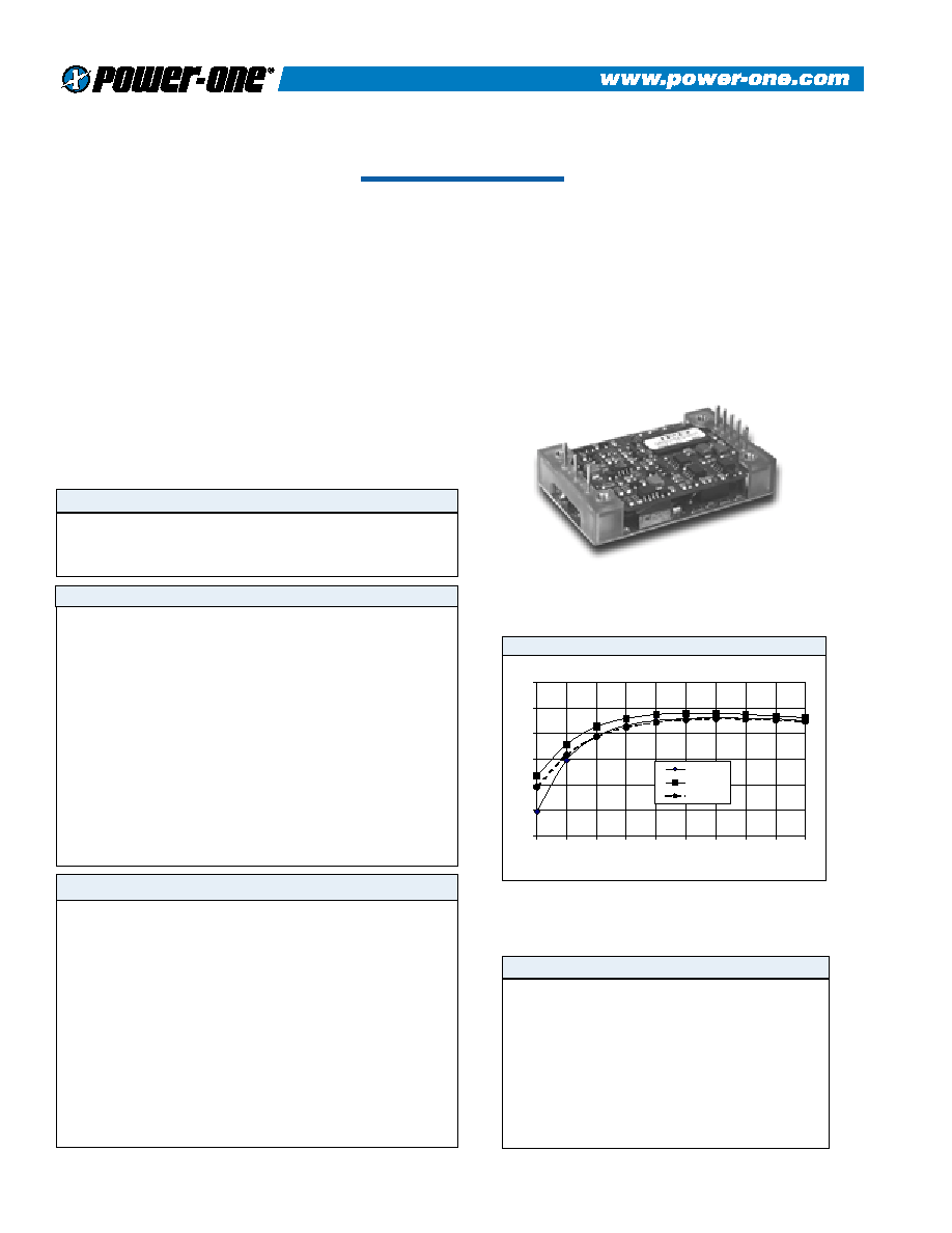
QBS single output DC/DC converters provide up to
120 Watts of output power in an industry standard,
quarter-brick footprint. The QBS converters feature
open-frame packaging, along with planar magnetics to
provide maximum useable power with minimal
thermal constraints. The QBS is especially suited to
telecom, networking, and industrial applications, and
is fully compatible with production board washing
processes.
� "Quarter-Brick"
� High Power Density Up
To 120W
� Open-Frame Packaging
� 100�C Baseplate Operation
� Water Washable
� Outputs From
2.5V to 15V
� 1500V Isolation
� Positive or Negative
Enable Logic
Input
Output
General
DESCRIPTION
FEATURES
QBS SERIES - 120 WATT
Setpoint Accuracy
�1%
Line Regulation V
in
Min. - V
in
Max., I
out
Rated
0.2% V
out
Load Regulation I
out
Min. - I
out
Max., V
in
Nom.
0.5% V
out
Remote Sense Headroom
0.5 VDC
Minimum Output Current
10 % l
out
Rated
Dynamic Regulation, Loadstep
25% I
out
Pk Deviation
4% V
out
Settling Time
500
�
s
Voltage Trim Range
�10%
Short Circuit And Overcurrent Protection
Shutdown
Current Limit Threshold Range, % of I
out
Rated
110 - 140%
Short Circuit Current Limit
200% I
out
OVP Trip Range
115 - 140% V
out
Nom.
UVP Trip Range
70 - 90% V
out
Nom.
OVP/UVP Type
Latching
QBS100ZG-ANT
60
65
70
75
80
85
90
10
20
30
40
50
60
70
80
90
100
LOAD%
EFFICIENCY
%
EFF. (36v)
EFF. (48v)
EFF. (75v)
Efficiency vs. Load (48V Input)
MTBF predictions may vary slightly from model to model.
Specifications typically at 25�C, normal line, and full load, unless otherwise stated.
Soldering Conditions: I/O pins, 260�C, ten seconds; fully compatible with
commercial wave-soldering equipment.
Safety: Agency approvals may vary from model to model. Please consult factory
for specific model information.
Units are water-washable and fully compatible with commercial spray or immersion
post wave-solder washing equipment.
Notes
Rev. 0
4/2001
2
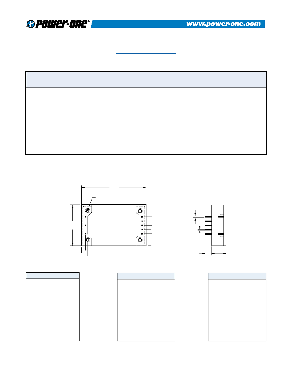
MECHANICAL DRAWING
QBS SERIES - 120 WATT
Thermal Impedance
Natural Convection
10.1 �C/W
100 LFM
8.0 �C/W
200 LFM
5.4 �C/W
300 LFM
4.4 �C/W
400 LFM
3.4 �C/W
Tolerances
Note:
Thermal impedance data is dependent on
many environmental factors. The exact
thermal performance should be validated for
specific application.
1
-V
in
2
On/Off
3
+V
in
4
-V
out
5
-Sense
6
Trim
7
+Sense
8
+V
out
Inches:
.XX � 0.020
.XXX � .010
Pin:
� 0.002 �
0.05
( Dimensions as listed unless otherwise specified.)
(Millimeters)
.X � 0.5
.XX � 0.25
P i n
Function
MODELS - (See the last page of this file for options.)
QBS
DIA 0.062"
0.450"(11.4mm)
0.150"(3.8mm)
-0.425"(-10.8mm)
0.815"(20.7mm)
-0.215"(-5.5mm)
0.600"(15.2mm)
0.300"(7.6mm)
0
8
7
6
5
4
3
2
1
M3X0.5 THROUGH 4PL
MOUNTING INSERTS
(1.6mm)
DIA 0.040"
(1.0mm)
0.18"
(4.6mm)
0.50"
(12.7mm)
2.28"
(57.9mm)
1.45"
(36.8mm)
BOTTOM VIEW
0
-0.14"
(-3.6mm) 0.070"
(1.8mm)
1.930"
(49.0mm)
2.000"
(50.8mm)
2PL
6PL
Vin
(Volts)
Vin Range
(Volts)
Iin Max.*
(Amps)
Vout
(Volts)
Iout Rated
(Amps)
Ripple & Noise
Pk-Pk (mV)
Efficiency
Typ. **
Model
24
24
24
24
24
48
48
48
48
48
48
48
48
48
18 - 36
18 - 36
18 - 36
18 - 36
18 - 36
36 - 75
36 - 75
36 - 75
36 - 75
36 - 75
36 - 75
36 - 75
36 - 75
36 - 75
2.90
3.50
5.20
6.80
6.80
1.40
1.70
2.50
3.30
4.00
3.30
2.50
3.45
4.00
2.5
3.3
5
12
15
2.5
3.3
5
12
12
15
3.3
5.0
15
15.00
15.00
15.00
8.33
6.67
15.00
15.00
15.00
8.33
10.00
6.67
20.0
20.0
8.0
100
100
100
150
150
100
100
100
150
150
150
100
100
150
76%
80%
84%
85%
85%
75%
78%
83%
86%
84%
86%
80%
82%
84%
QBS038YD-A
QBS050YE-A
QBS075YG-A
QBS100YH-A
QBS100YJ-A
QBS038ZD-A
QBS050ZE-A
QBS075ZG-A
QBS100ZH-A
QBS120ZH-A
QBS100ZJ-A
QBS066ZE-A
QBS100ZG-A
QBS120ZJ-A
Denotes advanced product release. Consult factory for product availability.
* Maximum input current at minimum input voltage, maximum rated output power.
** At nominal Vin, rated output.
3
OPTIONS
When ordering equipment options, use the following suffix information. Select the option(s) that
you prefer and add them to the model number. Example ordering options are located below the
options table.
OPTION
SUFFIX
APPLICABLE SERIES
REMARKS
Negative Logic
N
HAS, HBD, HBS, HES, LES, QBS,
QES, TES, TQD
TTL "Low" Turns Module ON
TTL "High" Turns Module OFF
Lucent Compatible Trim
T
HAS, HBD, HBS, HES, QBS, QES
Terminal Strip TS XWS, XWD, XWT
Trim
1
IAS, LES
Enable
2
IAD, IAS, LES, SMS
Trim and Enable
3
IAS, LES
Current Share
4
SMS
Headerless
Y
Encapsulated EWS, IWS, OWS
PIN LENGTH AND HEATSINK
OPTIONS
Standard Pin Length is 0.180"
(4.6mm)
0.110" (2.8mm) Pin Length
8
All Units (Except SMS)
0.150" (3.8mm) Pin Length
9
All Units (Except SMS)
0.24" (6.1mm) Horizontal Heatsink
1H
All Units (Except DIP, SIP, and SM
Packages)
Includes Thermal Pad
0.24" (6.1mm) Vertical Heatsink
1V
All Units (Except DIP, SIP, and SM
Packages)
Includes Thermal Pad
0.45" (11.4mm) Horizontal
Heatsink
2H
All Units (Except DIP, SIP, and SM
Packages)
Includes Thermal Pad
0.45" (11.4mm) Vertical Heatsink
2V
All Units (Except DIP, SIP, and SM
Packages)
Includes Thermal Pad
0.95" (24.1mm) Horizontal
Heatsink
3H
All Units (Except DIP, SIP, and SM
Packages)
Includes Thermal Pad
0.95" (24.1mm) Vertical Heatsink
3V
All Units (Except DIP, SIP, and SM
Packages)
Includes Thermal Pad
Example Options: HBS050ZG-ANT3V = HBS050ZG-A with negative logic, Lucent compatible trim, and
0.95" vertical heatsink.
LES015YJ-3N = LES015YJ with optional trim and enable, negative logic.
QBS066ZG-AT8 = QBS066ZG-A with Lucent compatible trim and 0.110" pin length.
NUCLEAR AND MEDICAL APPLICATIONS
Power-One products are not authorized for use as critical components in life support systems,
equipment used in hazardous environments, or nuclear control systems without the express written consent of the President of Power-One, Inc.
TECHNICAL REVISIONS
The appearance of products, including safety agency certifications pictured on labels, may change depending on the
date manufactured. Specifications are subject to change without notice.