
D
N
E
G
C
H
M
B
B
E
F
F
A
J
A2
K2
K1
A1
3
2
1
4
2
4
1
3
P - M8 THD
(4 TYP.)
L - DIA.
(2 TYP.)
(4 TYP.)
Dimension
Inches
Millimeters
A
5.906
150
B
2.697�0.02
68.5�0.2
C
1.575
40
D
1.535
39
E
1.260
32
F
1.181
30
G
0.906
23
H
0.787
20
J
0.630
16
K
0.276
7
L
0.256�0.008 Dia. Dia. 6.5�0.2
M
0.236
6
N
0.197
5
P
M8 Metric
M8
*AI-K2 connection made by external shorting bar.
Description:
Powerex Dual Diode
POW-R-BLOKTM Modules are
designed for use in applications
requiring AC to DC rectification in
isolated packaging. The modules
are isolated for easy mounting
with other components on com-
mon heatsinks. POW-R-BLOKTM
has been tested and recognized
by Underwriters Laboratories
(QQQX2 Power Switching
Semiconductors).
Features:
Isolated Mounting
Glass Passivated Chips
Metal Baseplate
Low Thermal Impedance
UL Recognized
A
Applications:
Battery Supplies
AC and DC Motor Power
Supplies
Ordering Information:
Select the complete eight digit
module part number you desire
from the table below.
Example: CD511625 is a
1600 Volt, 250 Ampere Dual Diode
POW-R-BLOKTM Module.
Voltage
Current Rating
Type
Volts (x100)
Amperes (x10)
CD51
12
25
16
D-123
Powerex, Inc., 200 Hillis Street, Youngwood, Pennsylvania 15697-1800 (724) 925-7272
Dual Diode
POW-R-BLOKTM Modules
250 Amperes/1200-1600 Volts
CD511225
CD511625
Outline Drawing
CD511225, CD511625
Dual Diode
POW-R-BLOKTM Modules
250 Amperes/1200-1600 Volts
A

D-124
Powerex, Inc., 200 Hillis Street, Youngwood, Pennsylvania 15697-1800 (724) 925-7272
CD511225, CD511625
Dual Diode POW-R-BLOKTM Modules
250 Amperes/1200-1600 Volts
Absolute Maximum Ratings
Characteristics
Symbol
CD511225
CD511625
Units
Peak Reverse Blocking Voltage
VRRM
1200
1600
Volts
Transient Peak Reverse Blocking Voltage (Non-Repetitive), t < 5ms
VRSM
1350
1700
Volts
DC Reverse Blocking Voltage
VR(DC)
960
1280
Volts
RMS On-State Current
IF(RMS)
390
390
Amperes
Average On-State Current, TC = 64�C
IF(AV)
250
250
Amperes
Peak One-Cycle Surge (Non-Repetitive) On-State Current (60Hz)
IFSM
5000
5000
Amperes
Peak One-Cycle Surge (Non-Repetitive) On-State Current (50Hz)
IFSM
4500
4500
Amperes
I2t (for Fusing), 8.3 milliseconds
I2t
100,000
100,000
A2sec
Storage Temperature
TSTG
-40 to 125
-40 to 125
�C
Operating Temperature
Tj
-40 to 125
-40 to 125
�C
Maximum Mounting Torque M6 Mounting Screw
--
26
26
in.-lb.
Maximum Mounting Torque M8 Terminal Screw
--
72
72
in.-lb.
Module Weight (Typical)
--
300
300
Grams
V Isolation
VRMS
2500
2500
Volts

D-125
Powerex, Inc., 200 Hillis Street, Youngwood, Pennsylvania 15697-1800 (724) 925-7272
CD511225, CD511625
Dual Diode POW-R-BLOKTM Modules
250 Amperes/1200-1600 Volts
Electrical and Thermal Characteristics,
Tj = 25�C unless otherwise specified
Characteristics
Symbol
Test Conditions
CD511225/CD511625
Units
Blocking State Maximums
Reverse Leakage Current, Peak
IRRM
Tj = 125�C, VRRM = Rated
30
mA
Conducting State Maximums
Peak On-State Voltage
VFM
IFM = 750A
1.3
Volts
Thermal Maximums
Thermal Resistance, Junction-to-Case
R (J-C)
Per Module
0.2
�C/Watt
Thermal Resistance, Case-to-Sink (Lubricated)
R (C-S)
Per Module
0.05
�C/Watt
D-126
Powerex, Inc., 200 Hillis Street, Youngwood, Pennsylvania 15697-1800 (724) 925-7272
CD511225, CD511625
Dual Diode POW-R-BLOKTM Modules
250 Amperes/1200-1600 Volts
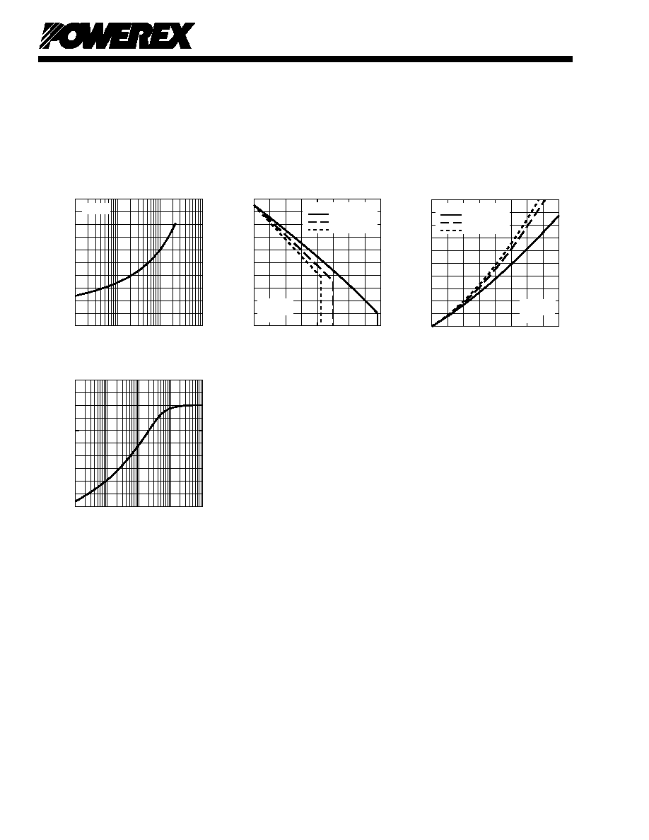
INSTANTANEOUS ON-STATE CURRENT, I
FM
,
(AMPERES)
MAXIMUM
ON-STATE CHARACTERISTICS
10
1
10
2
10
3
10
4
INSTANTANEOUS ON-STATE VOLTAGE, V
FM
, (VOLTS)
0
0.5
1.0
1.5
2.0
2.5
T
j
= 25
o
C
MAXIMUM
ALLOWABLE CASE TEMPERATURE
AVERAGE ON-STATE CURRENT, I
F(AV)
,
(AMPERES)
MAXIMUM ALLOWABLE CASE TEMPERATURE, T
C
, (
o
C)
0
100
200
300
400
30
50
70
90
110
130
RESISTIVE
INDUCTIVE
LOAD
DC
SINGLE-PHASE
THREE-PHASE
OPERATION
MAXIMUM
ON-STATE POWER DISSIPATION
AVERAGE ON-STATE CURRENT, I
F(AV)
,
(AMPERES)
0
400
100
300
MAXIMUM POWER DISSIPATION, P
AV(MAX)
, (WATTS)
0
100
200
300
400
500
200
RESISTIVE
INDUCTIVE
LOAD
DC
SINGLE-PHASE
THREE-PHASE
OPERATION
TIME, t, (SECONDS)
TRANSIENT THERMAL IMPEDANCE
CHARACTERISTICS (JUNCTION-TO-CASE)
TRANSIENT THERMAL IMPEDANCE, Z
(J-C)
(t), (
o
C/WATT)
10
-3
10
-2
10
0
10
1
10
-1
0
0.05
0.10
0.15
0.20
0.25