1
CIB Module
Three Phase Converter +
Three Phase Inverter + Brake
15 Amperes/600 Volts
CM15MD-12H
Powerex, Inc., 200 Hillis Street, Youngwood, Pennsylvania 15697-1800 (724) 925-7272
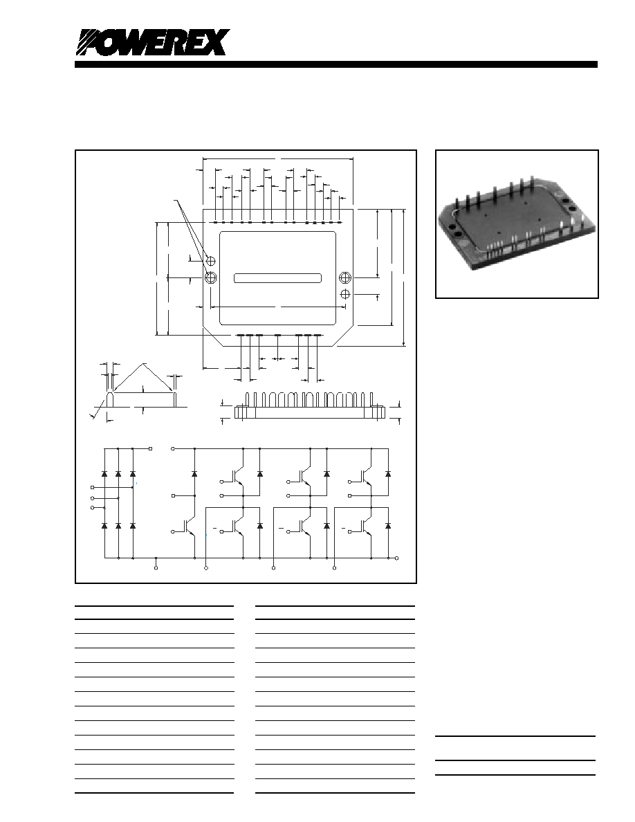
Outline Drawing and Circuit Diagram
R
S
T
N
P P1
B
G
U
V
W
G
EU
G
EV
G
EW
B
U
V
W
GU
GV
GW
E
LABEL
R
S
T
U
V
W
P P1 N GU EU GV EV GW EW GU GV GW
E
B
(4 PLACES)
GB
A
B
C
D
E
D
F
H
H
G
J
K
L
K
K
L
L
K
K
K
K
N
H
H
P
P
H
H
Q
R
Z
U
Q
Y
MAIN TERMINAL
CONTROL
TERMINAL
S
W
V
30
∞
X
"T" THICK
Description:
Powerex CIB Modules are
designed for use in switching
applications. Each module
consists of a three phase diode
converter section, a three phase
IGBT inverter section and a brake
section. All components and
interconnects are isolated from the
heat sinking baseplate, offering
simplified system assembly and
thermal management.
Features:
Low Drive Power
Low V
CE(sat)
Discrete Super-Fast
Recovery (70ns)
Free-Wheel Diodes
High Frequency Operation
(20-25 kHz)
Isolated Baseplate for Easy
Heat Sinking
Applications:
AC Motor Control
Motion/Servo Control
General Purpose Inverters
Robotics
Ordering Information:
Example: Select the complete nine
digit module part number you
desire from the table below - i.e.
CM15MD-12H is a 600V (V
CES
),
15 Ampere CIB Power Module.
Current Rating
VCES
Type
Amperes
Volts (x 50)
CM
15
12
Dimensions
Inches
Millimeters
A
3.54
90.0
B
2.52
64.0
C
1.26
32.0
D
0.35
9.0
E
3.15
80.0
F
0.20
5.0
G
0.30
7.5
H
0.32
8.0
J
0.48
12.28
K
0.10
2.54
L
0.30
7.62
M
0.19
4.8
Dimensions
Inches
Millimeters
N
0.65
16.5
P
0.49
12.5
Q
1.04
26.5
R
2.09
53.0
S
0.08
2.0
T
0.02
0.5
U
2.13
54.0
V
0.04
1.0
W
0.03
0.8
X
0.32
8.0
Y
0.21
5.3
Z
0.20
5.0

2
CM15MD-12H
CIB Module
Three Phase Converter + Three Phase Inverter + Brake
15 Amperes/600 Volts
Powerex, Inc., 200 Hillis Street, Youngwood, Pennsylvania 15697-1800 (724) 925-7272
Absolute Maximum Ratings,
T
j
= 25∞C unless otherwise specified
Characteristics
Symbol
CM15MD-12H
Units
Power Device Junction Temperature
T
j
-40 to 150
∞
C
Storage Temperature
T
stg
-40 to 125
∞
C
Mounting Torque, M4 Mounting Screws
--
13
in-lb
Module Weight (Typical)
--
60
Grams
Isolation Voltage, AC 1 minute, 60Hz
V
RMS
2500
Volts
Converter Part
Repetitive Peak Reverse Voltage
V
RRM
800
Volts
Recommended AC Input Voltage
E
a
220
Volts
DC Output Current
I
O
15
Amperes
Surge (Non-repetitive) Forward Current
I
FSM
150
Amperes
I
2
t for Fusing
I
2
t
93
A
2
s
IGBT Inverter Part
Collector-Emitter Voltage (G-E Short)
V
CES
600
Volts
Gate-Emitter Voltage (C-E Short)
V
GES
±
20
Volts
Collector Current
I
C
15
Amperes
Collector Current (Pulse)*
I
CM
30
Amperes
Emitter Current**
I
E
15
Amperes
Emitter Current** (Pulse)*
I
EM
30
Amperes
Maximum Collector Dissipation
P
C
45
Watts
Brake Part
Collector-Emitter Voltage (G-E Short)
V
CES
600
Volts
Gate-Emitter Voltage (C-E Short)
V
GES
±
20
Volts
Collector Current
I
C
15
Amperes
Collector Current (Pulse)*
I
CM
30
Amperes
Collector Dissipation
P
C
45
Watts
Repetitive Peak Reverse Voltage (Clamp Diode Part)
V
RRM
600
Volts
Forward Current (Clamp Diode Part)
I
FM
15
Amperes
* Pulse width and repetition rate should be such that device junction temperature does not exceed maximum rating.
** Characteristics of the anti-parallel emitter-collector free-wheel diode.

3
CM15MD-12H
CIB Module
Three Phase Converter + Three Phase Inverter + Brake
15 Amperes/600 Volts
Powerex, Inc., 200 Hillis Street, Youngwood, Pennsylvania 15697-1800 (724) 925-7272
Electrical and Mechanical Characteristics,
T
j
= 25∞C unless otherwise specified
Characteristics
Symbol
Test Conditions
Min.
Typ.
Max.
Units
Converter Sector
Repetitive Reverse Current
I
RRM
V
R
= V
RRM
, T
j
= 150
∞
C
--
--
8
mA
Forward Voltage Drop
V
FM
I
F
= 15A
--
--
1.5
Volts
Thermal Resistance (Junction-to-Fin)
R
th(j-f)
Per Diode
--
--
3.6
∞
C/W
Brake Sector
Collector-Emitter Saturation Voltage
V
CE(sat)
V
GE
= 15V, I
C
= 15A, T
j
= 25
∞
C
--
2.1
2.8
Volts
V
GE
= 15V, I
C
= 15A, T
j
= 150
∞
C
--
2.15
--
Volts
Collector Cutoff Current
I
CES
V
CE
= V
CES
, V
GE
= 0V, T
j
= 25
∞
C
--
--
1
mA
Gate-Emitter Threshold Voltage
V
GE(th)
I
C
= 1.5mA, V
CE
= 10V
4.5
6.0
7.5
Volts
Gate-Emitter Cutoff Current
I
GES
V
GE
= V
GES
, V
CE
= 0V
--
--
0.5
µ
A
Input Capacitance
C
ies
--
--
1.5
nF
Output Capacitance
C
oes
V
GE
= 0V, V
CE
= 10V
--
--
1.2
nF
Reverse Transfer Capacitance
C
res
--
--
0.3
nF
Total Gate Charge
Q
G
V
CC
= 300V, I
C
= 15A, V
GE
= 15V
--
45
--
nC
Forward Voltage Drop
V
FM
I
F
= 15A
--
--
1.5
Volts
Thermal Resistance (Junction-to-Fin)
R
th(j-f)
Per IGBT
--
--
2.8
∞
C/W
Per Clamp Diode
--
--
3.6
∞
C/W

4
CM15MD-12H
CIB Module
Three Phase Converter + Three Phase Inverter + Brake
15 Amperes/600 Volts
Powerex, Inc., 200 Hillis Street, Youngwood, Pennsylvania 15697-1800 (724) 925-7272
Electrical and Mechanical Characteristics,
T
j
= 25∞C unless otherwise specified
Characteristics
Symbol
Test Conditions
Min.
Typ.
Max.
Units
IGBT Inverter Sector
Collector Cutoff Current
I
CES
V
CE
= V
CES
, V
GE
= 0V
--
--
1
mA
Gate-Emitter Threshold Voltage
V
GE(th)
V
CE
= 10V, I
C
= 1mA
4.5
6.0
7.5
Volts
Gate-Emitter Cutoff Current
I
GES
V
GE
= V
GES
, V
CE
= 0V
--
--
0.5
µ
A
Collector-Emitter Saturation Voltage
V
CE(sat)
V
GE
= 15V, I
C
= 15A, T
j
= 25
∞
C
--
2.1
2.8
Volts
V
GE
= 15V, I
C
= 15A, T
j
= 150
∞
C
--
2.15
--
Volts
Input Capacitance
C
ies
--
--
1.5
nF
Output Capacitance
C
oes
V
GE
= 0V, V
CE
= 10V
--
--
1.2
nF
Reverse Transfer Capacitance
C
res
--
--
0.3
nF
Total Gate Charge
Q
G
V
CC
= 300V, I
C
= 15A, V
GE
= 15V
--
45
--
nC
Resistive
Turn-on Delay Time
t
d(on)
V
GE1
= V
GE2
= 15V,
--
--
120
nS
Load
Rise Time
t
r
V
CC
= 300V, I
C
= 15A,
--
--
300
nS
Switching
Turn-off Delay Time
t
d(off)
R
g
= 42
,
--
--
200
nS
Times
Fall Time
t
f
Resistive Load
--
--
300
nS
Emitter-Collector Voltage
V
EC
I
E
= 15A, V
GE
= 0V
--
--
2.8
Volts
Reverse Recovery Time
t
rr
I
E
= 15A, V
GE
= 0V,
--
--
110
nS
Reverse Recovery Charge
Q
rr
di
E
/dt = -30A/
µ
s
--
0.04
--
µ
C
Thermal Resistance (Junction-to-Fin)
R
th(j-f)
Per IGBT
--
--
2.8
∞
C/W
Per FWDi
--
--
3.5
∞
C/W
5
CM15MD-12H
CIB Module
Three Phase Converter + Three Phase Inverter + Brake
15 Amperes/600 Volts
Powerex, Inc., 200 Hillis Street, Youngwood, Pennsylvania 15697-1800 (724) 925-7272
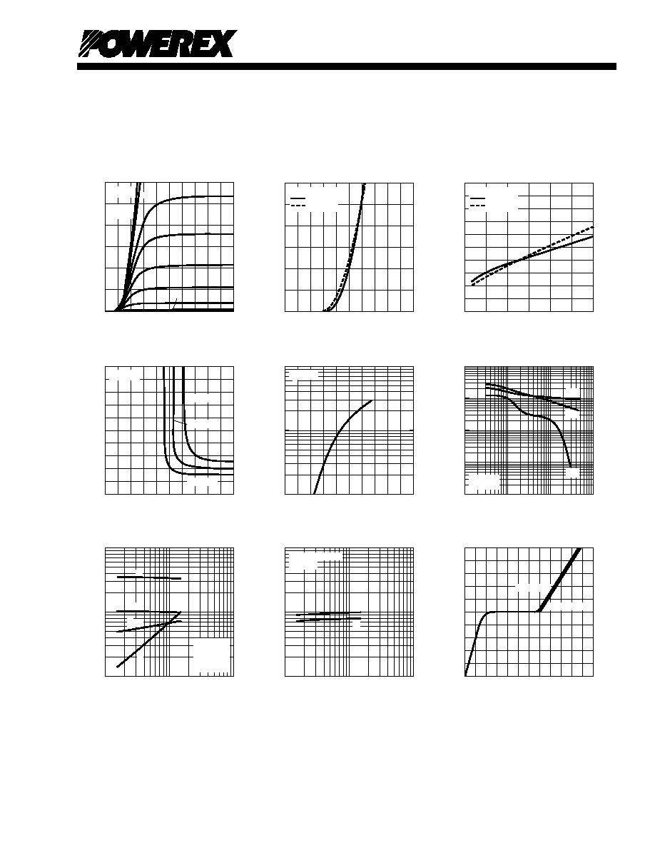
V
GE
=
20V
COLLECTOR-EMITTER VOLTAGE, V
CE
, (VOLTS)
COLLECTOR CURRENT, I
C
, (AMPERES)
OUTPUT CHARACTERISTICS
(TYPICAL)
0
2
4
6
8
10
10
0
15
12
11
8
7
T
j
= 25
o
C
20
30
10
9
GATE-EMITTER VOLTAGE, V
GE
, (VOLTS)
COLLECTOR CURRENT, I
C
, (AMPERES)
TRANSFER CHARACTERISTICS
(TYPICAL)
0
4
8
12
16
20
0
30
20
10
V
CE
= 10V
T
j
= 25
∞
C
T
j
= 125
∞
C
COLLECTOR-CURRENT, I
C
, (AMPERES)
COLLECTOR-EMITTER
SATURATION VOLTAGE, V
CE(sat)
, (VOLTS)
COLLECTOR-EMITTER
SATURATION VOLTAGE CHARACTERISTICS
(TYPICAL)
5
0
10
4
3
2
1
0
V
GE
= 15V
T
j
= 25
∞
C
T
j
= 125
∞
C
30
20
GATE-EMITTER VOLTAGE, V
GE
, (VOLTS)
COLLECTOR-EMITTER
SATURATION VOLTAGE, V
CE(sat)
, (VOLTS)
COLLECTOR-EMITTER
SATURATION VOLTAGE CHARACTERISTICS
(TYPICAL)
10
0
4
8
12
16
20
8
6
4
2
0
T
j
= 25
∞
C
I
C
= 6A
I
C
= 30A
I
C
= 15A
0
0.8
1.6
2.4
3.2
4.0
10
0
EMITTER-COLLECTOR VOLTAGE, V
EC
, (VOLTS)
FREE-WHEEL DIODE
FORWARD CHARACTERISTICS
(TYPICAL)
10
1
10
2
EMITTER CURRENT, I
E
, (AMPERES)
T
j
= 25
∞
C
COLLECTOR-EMITTER VOLTAGE, V
CE
, (VOLTS)
CAPACITANCE, C
ies
, C
oes
, C
res
, (nF)
CAPACITANCE VS. V
CE
(TYPICAL)
10
-1
10
0
10
2
10
0
10
-1
10
1
10
-2
10
-3
V
GE
= 0V
f = 1MHz
10
1
C
ies
C
oes
C
res
COLLECTOR CURRENT, I
C
, (AMPERES)
SWITCHING TIME, (ns)
HALF-BRIDGE
SWITCHING CHARACTERISTICS
(TYPICAL)
10
3
10
0
10
1
10
2
10
2
10
1
t
d(off)
t
d(on)
t
r
V
CC
= 300V
V
GE
=
±
15V
R
G
= 42
T
j
= 125
∞
C
t
f
EMITTER CURRENT, I
E
, (AMPERES)
REVERSE RECOVERY TIME, t
rr
, (ns)
REVERSE RECOVERY CHARACTERISTICS
(TYPICAL)
10
3
10
0
10
1
10
2
10
2
10
1
t
rr
I
rr
10
1
10
0
10
-1
REVERSE RECOVERY CURRENT, I
rr
, (AMPERES)
di/dt = -30A/
µ
sec
T
j
= 25
∞
C
GATE CHARGE, Q
G
, (nC)
GATE-EMITTER VOLTAGE, V
GE
, (VOLTS)
GATE CHARGE, V
GE
20
0
10
20
30
16
12
8
4
0
40
60
50
V
CC
= 300V
V
CC
= 200V