Powerex, Inc., Hillis Street, Youngwood, Pennsylvania 15697 (724) 925-7272
POW-R-BLOK
TM
Dual Diode Isolated Module
600 Amperes / Up to 2400 Volts
Revision Date: 11/5/2002
LD41__60
Ordering Information
:
Select the complete eight-digit
module part number from the table
below.
Example: LD412460 is a 2400V,
600 Ampere Dual Diode Isolated
POW-R-BLOK
TM
Module.
Type
Voltage
Volts
(x100)
Current
Amperes
(x10)
LD41 08
10
12 to 24
60
LD41__60
Dual Diode
POW-R-BLOK
TM
Module
600 Amperes / 800-2400 Volts
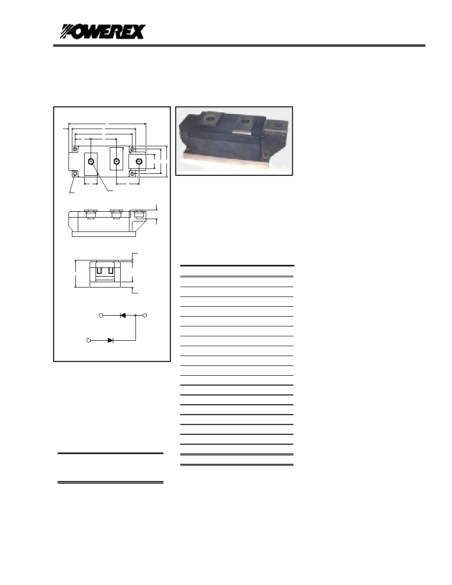
LD41 Outline Dimensions
Dimension
Inches Millimeters
A 5.91 150.0
B 4.88 124.0
C 4.41 112.0
D 2.36 60.0
E 2.05 52.0
F 1.97 50.0
G 1.89 48.0
H 1.73 44.0
J 1.22 31.0
K 1.10 28.0
L 1.00 25.4
M 0.69 17.5
N 0.39 10.0
P M10
Metric M10
Q
0.26 Dia.
6.5 Dia.
R 0.24 6.0
S 0.12 3.0
T
.110 x .032
2.5 x 0.8
Note: Dimensions are for reference only.
Description:
Powerex Dual Diode Modules are
designed for use in applications
requiring rectification and isolated
packaging. The modules are isolated
for easy mounting with other
components on a common heatsink.
POW-R-BLOK
TM
has been tested and
recognized by the Underwriters
Laboratories.
Features:
T Electrically Isolated Heatsinking
T Aluminum Nitride Isolator
T Compression Bonded Elements
T Metal Baseplate
T Low Thermal Impedance
for Improved Current Capability
T UL Recognized
Benefits:
T No Additional Insulation
Components Required
T Easy Installation
T No Clamping Components
Required
T Reduce Engineering Time
Applications:
T Bridge Circuits
T AC & DC Motor Drives
T Battery Supplies
T Power Supplies
T Large IGBT Circuit Front Ends
CONNECTION DIAGRAM
1
2
3
J
F
C
B
A
R
L
H
Q - DIA. (4
TYP.)
P - M10 THD (3
TYP.)
K
D
G
M
N
S
E
1
2
3
OUTLINE DRAWING

Powerex, Inc., Hillis Street, Youngwood, Pennsylvania 15697 (724) 925-7272
POW-R-BLOK
TM
Dual Diode Isolated Module
600 Amperes / Up to 2400 Volts
Revision Date: 11/5/2002
LD41__60
Absolute Maximum Ratings
Characteristics Conditions
Symbol
Units
Repetitive Peak Reverse Blocking Voltage
V
RRM
up to 2400
V
Non-Repetitive Peak Reverse Blocking Voltage
(t < 5 msec)
V
RSM
V
RRM
+ 100
V
RMS Forward Current
I
F(RMS)
950 A
Average Forward Current
180� Conduction, T
C
=106�C I
F(AV)
600 A
Peak One Cycle Surge Current, Non-Repetitive
60 Hz, 100% V
RRM
reapplied
50 Hz, 100% V
RRM
reapplied
I
FSM
I
FSM
21000
19000
A
A
Peak Three Cycle Surge Current, Non-Repetitive
60 Hz, 100%V
RRM
reapplied
I
FSM
15,500 A
Peak Ten Cycle Surge Current, Non-Repetitive
60 Hz, 100% V
RRM
reapplied
I
FSM
13,000
A
I
2
t for Fusing for One Cycle
8.3 milliseconds
10 milliseconds
I
2
t
I
2
t
1,840,000
1,810,000
A
2
sec
A
2
sec
Operating Temperature
T
J
-40
to
+150 �C
Storage Temperature
T
stg
-40
to
+150 �C
Max. Mounting Torque, M6 Mounting Screw
55
6
in. � Lb.
Nm
Max. Mounting Torque, M10 Terminal Screw
110
12
in. � Lb.
Nm
Module Weight, Typical
1500
g
3.30
lb
V Isolation @ 25C
V
rms
3000 V

Powerex, Inc., Hillis Street, Youngwood, Pennsylvania 15697 (724) 925-7272
POW-R-BLOK
TM
Dual Diode Isolated Module
600 Amperes / Up to 2400 Volts
Revision Date: 11/5/2002
LD41__60
Electrical Characteristics, T
J
=25�C unless otherwise specified
Characteristics Symbol
Test
Conditions
Min.
Max.
Units
Repetitive Peak Reverse Leakage Current
I
RRM
Up to 2400V, T
J
=150�C
40
mA
Peak On-State Voltage
V
FM
T
J
=150�C, I
FM
=1800A
1.19
V
Threshold Voltage, Low-level
Slope Resistance, Low-level
V
(TO)1
r
T1
T
J
= 150�C, I = 15%I
F(AV)
to I
F(AV)
0.747
0.243
V
m
Threshold Voltage, High-level
Slope Resistance, High-level
V
(TO)2
r
T2
T
J
= 150�C, I = I
F(AV)
to I
FSM
0.914
0.145
V
m
V
TM
Coefficients, Full Range
T
J
= 150�C, I = 15%I
F(AV)
to I
FSM
V
TM
= A+ B Ln I +C I + D Sqrt I
A =
B =
C =
D =
5.05E-01
3.44E-02
8.13E-05
6.57E-03
Thermal Characteristics
Characteristics Symbol
Max.
Units
Thermal Resistance, Junction to Case
R
J-C
Per Module, both conducting
Per Junction, both conducting
0.0325
0.0650
�C/W
�C/W
Thermal Impedance Coefficients
Z
J-C
Z
J-C
= K
1
(1-exp(-t/
1
))
+ K
2
(1-exp(-t/
2
))
+ K
3
(1-exp(-t/
3
))
+ K
4
(1-exp(-t/
4
))
K
1
= 8.03E-04
K
2
= 1.03E-02
K
3
= 1.64E-02
K
4
= 3.75E-02
1
= 3.39E-04
2
= 3.15E-03
3
= 1.06E-01
4
= 2.066
Thermal Resistance, Case to Sink Lubricated
R
C-S
Per Module
0.01
�C/W
Powerex, Inc., Hillis Street, Youngwood, Pennsylvania 15697 (724) 925-7272
POW-R-BLOK
TM
Dual Diode Isolated Module
600 Amperes / Up to 2400 Volts
Revision Date: 11/5/2002
LD41__60
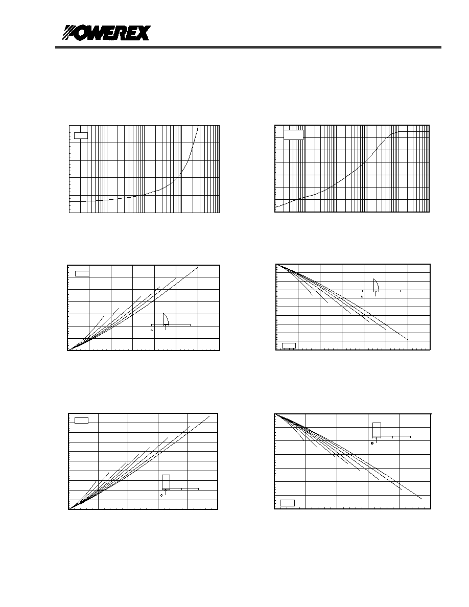
Maximum Transient Thermal Impedance
0
0.01
0.02
0.03
0.04
0.05
0.06
0.07
0.001
0.01
0.1
1
10
100
Time - t - Seconds
Thermal Impedance - Zjc - �
C
/W
(Junction to Case)
LD41N
Maximum On-State Forward Voltage Drop
0.00
1.00
2.00
3.00
4.00
5.00
10
100
1000
10000
100000
Instantaneous On-State Current - Ifm - Amperes
O
n
-S
ta
te
V
o
lta
g
e
- V
f
m - V
o
lts
( Tj = 150 �C )
LD41N
0
180
360
CONDUCTION ANGLE
M axim um O n-State Pow er Dissipation
15�
30�
60�
90�
120�
180�
0
100
200
300
400
500
600
700
0
100
200
300
400
500
600
700
Average O n-State Current - If(av) - Am peres
M
ax.
P
o
w
e
r
D
i
ssi
pat
i
on P
e
r
D
i
ode -
Wat
t
s
(Sinusoidal W aveform )
LD41N
0
180
360
CONDUCTION ANGLE
Maximum Allowable Case Temperature
120�
90�
60�
30�
15�
180�
100
105
110
115
120
125
130
135
140
145
150
0
100
200
300
400
500
600
700
Average On-State Current - If(av) - Amperes
M
ax. C
ase Tem
p
er
at
ur
e -
Tcase -
�
C
(Sinusoidal Waveform)
LD41N
0
180
360
CONDUCTION ANGLE
Maximum On-State Power Dissipation
90�
60�
30�
120�
180�
270�
15�
360�
0
100
200
300
400
500
600
700
800
900
1000
0
200
400
600
800
1000
Average On-State Current - If(av) - Amperes
M
ax. Pow
e
r
D
i
ssipation Per
D
i
ode - Watts
(Rectangular Waveform)
LD41N
0
180
360
CONDUCTION ANGLE
Maximum Allowable Case Temperature
270�
180�
120�
90�
60�
30�
15�
360�
80
90
100
110
120
130
140
150
0
200
400
600
800
1000
Average On-State Current - If(av) - Amperes
M
ax. C
ase T
e
m
p
er
at
u
r
e -
T
case -
�
C
(Rectangular Waveform)
LD41N
Powerex, Inc., Hillis Street, Youngwood, Pennsylvania 15697 (724) 925-7272
POW-R-BLOK
TM
Dual Diode Isolated Module
600 Amperes / Up to 2400 Volts
Revision Date: 11/5/2002
LD41__60
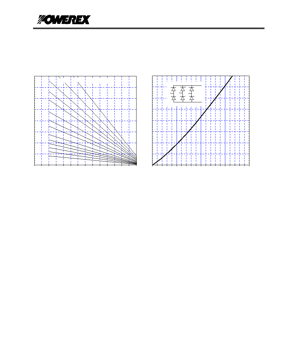
Six-Pulse Bridge Circuit Total Power Dissipation & Maximum Rated Output Current With Sink to Ambient
Resistance of Heatsink as a Parameter.
Total Power Dissipation vs Maximum Rated Output Current
0
500
1000
1500
2000
2500
3000
3500
4000
0
500
1000
1500
2000
Maximum Bridge Output Current (A)
0
500
1000
1500
2000
2500
3000
3500
4000
Total
P
o
wer Di
s
s
i
p
ati
o
n
(W)
Powerex
LD41--60
Pow-R-Blok
6-Pulse Bridge
0
500
1000
1500
2000
2500
3000
3500
4000
0
20
40
60
80
100
120
140
Ambient Temperature (C)
Tot
a
l
Pow
e
r
D
i
s
s
i
pa
tio
n
(W)
0.30
0.20
0.15
0.12
0.10
0.08
0.06
0.05
0.04
0.03
0.025
0.02
0.015
0.01
Rth S-A (C/W)