Powerex, Inc., 200 E. Hillis Street, Youngwood, Pennsylvania 15697-1800 (724) 925-7272
IntellimodTM L-Series
Three Phase
IGBT Inverter
25 Amperes/1200 Volts
PM25CLB120
1
Description:
Powerex IntellimodTM Intelligent
Power Modules are isolated base
modules designed for power
switching applications operating
at frequencies to 20kHz. Built-in
control circuits provide optimum
gate drive and protection for the
IGBT and free-wheel diode
power devices.
Features:
£
Complete Output Power
Circuit
£
Gate Drive Circuit
£
Protection Logic
≠ Short Circuit
≠ Over Temperature
Using On-chip
Temperature Sensing
≠ Under Voltage
£
Low Loss Using 5th
Generation IGBT Chip
Applications:
£
Inverters
£
UPS
£
Motion/Servo Control
£
Power Supplies
Ordering Information:
Example: Select the complete
part number from the table below
-i.e. PM25CLB120 is a 1200V,
25 Ampere IntellimodTM Intelligent
Power Module.
Type
Current Rating
V
CES
Amperes
Volts (x 10)
PM
25
120
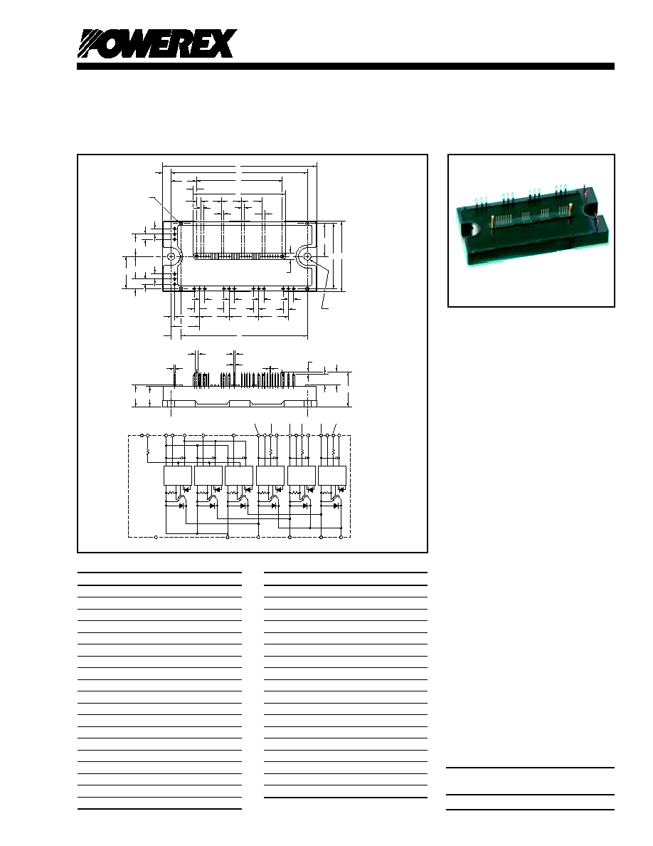
Outline Drawing and Circuit Diagram
Dimensions
Inches
Millimeters
A 4.72 120.0
B 2.17 55.0
C 0.63 16.0
D 4.17 106.0
E 0.28 7.0
F 0.78 19.75
G 2.62 66.5
H 0.13 3.25
J 0.63 16.0
K 0.08 2.0
L 0.10 2.5
M 2.81 71.5
N 0.20 5.0
P 0.31 7.75
Q 3.87 98.25
R 0.87 22.0
S 0.10 2.5
T 0.77 19.5
U 0.91 23.0
Dimensions
Inches
Millimeters
V 0.16 4.0
W 1.01 25.75
X 2.00 50.75
Y 0.69 17.5
Z 0.30 7.5
AA 0.98 25.0
AB 0.10 Dia.
Dia. 2.5
AC 0.22 Dia.
Dia. 5.5
AD 0.67 17.0
AE 0.10 Dia.
Dia. 2.5
AF 0.33 8.5
AG 0.08 2.0
AH 0.41 10.5
AJ 1.08 27.5
AK 0.04 1.0
AL 0.02 Sq.
Sq. 0.5
AM 0.06 1.5
AN 0.04 1.0
V
CC
S
I
GND
GND
OUT
F
O
IN
OT
V
CC
S
I
GND
GND
OUT
F
O
IN
OT
V
CC
S
I
GND
GND
OUT
F
O
IN
OT
V
CC
S
I
GND
GND
OUT
F
O
IN
OT
P
U
UN
NC FO VNC
WN
VN1
VN
VWPC
WP
WFO
VWP1
VVPC
VP
VFO
VVP1
VUPC
UP
UFO
VUP1
V
W
N
NC
V
CC
S
I
GND
GND
OUT
F
O
IN
OT
V
CC
S
I
GND
GND
OUT
F
O
IN
OT
19 F
O
17 V
N
14 V
N1
11 W
P
8 V
VP1
2 U
FO
6 V
FO
5 V
VPC
3 U
P
7 V
P
9 V
WPC
10 W
FO
12 V
WP1
1 V
UPC
4 V
UP1
16 U
N
15 NC
18 W
N
13 V
NC
TERMINAL
CODE
E
D
A
G
F
L
M
H
J
J
J
K
K
K
K
V
AB
(4 PLACES)
V
N
W
X B
V
V
V
V
V
V
V
V
S
T
U
U
U
R
P
Q
AC
(2 PLACES)
AJ
AH
AF
AG
AL
AN
AK
C
AD
AE
(2 PLACES)
AM
V
V
Y
Y
Z
AA
N
P
1
5
9
13
19
W
V
U
B

PM25CLB120
IntellimodTM L-Series
Three Phase IGBT Inverter
25 Amperes/1200 Volts
2
Powerex, Inc., 200 E. Hillis Street, Youngwood, Pennsylvania 15697-1800 (724) 925-7272
3
PM25CLB120
IntellimodTM L-Series
Three Phase IGBT Inverter
25 Amperes/1200 Volts
Powerex, Inc., 200 E. Hillis Street, Youngwood, Pennsylvania 15697-1800 (724) 925-7272
Absolute Maximum Ratings, T
j
= 25∞C unless otherwise specified
Characteristics
Symbol
PM25CLB120
Units
Power Device Junction Temperature
T
j
-20 to 150
∞C
Storage Temperature
T
stg
-40 to 125
∞C
Module Case Operating Temperature (See T
C
Measurement point Illustration)
T
C
-20 to 100
∞C
Mounting Torque, M5 Mounting Screws
--
31
in-lb
Module Weight (Typical)
--
340
Grams
Supply Voltage, Surge (Applied between P - N)
V
CC(surge)
1000
Volts
Self-protection Supply Voltage Limit (Short Circuit protection Capability)*
V
CC(prot.)
800
Volts
Isolation Voltage, AC 1 minute, 60Hz Sinusoidal
V
ISO
2500
Volts
*VD = 13.5 ~ 16.5V, Inverter Part, Tj = 125∞C
IGBT Inverter Sector
Collector-Emitter Voltage (V
D
= 15V, V
CIN
= 15V)
V
CES
1200
Volts
Collector Current (T
C
= 25∞C)
±I
C
25
Amperes
Peak Collector Current (T
C
= 25∞C)
±I
CP
50
Amperes
Collector Dissipation (T
C
= 25∞C)
P
C
148
Watts
Control Sector
Supply Voltage (Applied between V
UP1
-V
UPC
, V
VP1
-V
VPC
, V
WP1
-V
WPC
, V
N1
-V
NC
)
V
D
20
Volts
Input Voltage (Applied between U
P
-V
UPC
, V
P
-V
VPC
, W
P
-V
WPC
, U
N
- V
N
- W
N
-V
NC
)
V
CIN
20
Volts
Fault Output Supply Voltage
V
FO
20
Volts
(Applied between U
FO
-V
UPC
, V
FO
-V
VPC
, W
FO
-V
WPC
, F
O
-V
NC
)
Fault Output Current (U
FO
, V
FO
, W
FO
, F
O
Terminals)
I
FO
20
mA
Electrical and Mechanical Characteristics, T
j
= 25∞C unless otherwise specified
Characteristics Symbol Test Conditions Min. Typ. Max. Units
IGBT Inverter Sector
Collector-Emitter Cutoff Current I
CES
V
CE
= V
CES
, V
D
= 15V, T
j
= 25∞C -- -- 1.0 mA
V
CE
= V
CES
, V
D
= 15V, T
j
= 125∞C -- -- 10 mA
Diode Forward Voltage V
EC
-I
C
= 25A, V
CIN
= 15V, V
D
= 15V -- 2.5 3.5 Volts
Collector-Emitter Saturation Voltage V
CE(sat)
V
D
= 15V, V
CIN
= 0V, I
C
= 25A, -- 1.9 -- Volts
T
j
= 25∞C
V
D
= 15V, V
CIN
= 0V, I
C
= 25A, -- 1.9 -- Volts
T
j
= 125∞C
Inductive Load Switching Times t
on
0.5 1.0 2.5 µs
t
rr
V
D
= 15V, V
CIN
= 0 15V -- 0.15 0.3 µs
t
C(on)
V
CC
= 600V, I
C
= 25A -- 0.4 1.0 µs
t
off
T
j
= 125∞C -- 2.0 3.0 µs
t
C(off)
-- 0.7 1.2 µs

PM25CLB120
IntellimodTM L-Series
Three Phase IGBT Inverter
25 Amperes/1200 Volts
2
Powerex, Inc., 200 E. Hillis Street, Youngwood, Pennsylvania 15697-1800 (724) 925-7272
3
PM25CLB120
IntellimodTM L-Series
Three Phase IGBT Inverter
25 Amperes/1200 Volts
Powerex, Inc., 200 E. Hillis Street, Youngwood, Pennsylvania 15697-1800 (724) 925-7272
Electrical and Mechanical Characteristics, T
j
= 25∞C unless otherwise specified
Characteristics Symbol Test Conditions Min. Typ. Max. Units
Control Sector
Short Circuit Trip Level SC -20∞C T
j
125∞C, V
D
= 15V 50 -- -- Amperes
Short Circuit Current Delay Time t
off(SC)
V
D
= 15V -- 10 -- µs
Over Temperature Protection OT Trip Level 135 145 155 ∞C
(Detect T
j
of IGBT Chip) OT
R
Reset Level -- 125 -- ∞C
Supply Circuit Under-voltage Protection UV Trip Level 11.5 12.0 12.5 Volts
(-20 T
j
125∞C) UV
R
Reset Level -- 12.5 -- Volts
Circuit Current I
D
V
D
= 15V, V
CIN
= 15V, V
N1
-V
NC
-- 15 25 mA
V
D
= 15V, V
CIN
= 15V, V
XP1
-V
XPC
-- 5 10 mA
Input ON Threshold Voltage V
th(on)
Applied between U
P
-V
UPC
, 1.2 1.5 1.8 Volts
Input OFF Threshold Voltage V
th(off)
V
P
-V
VPC
, W
P
-V
WPC
, U
N
- V
N
- W
N
-V
NC
1.7 2.0 2.3 Volts
Fault Output Current* I
FO(H)
V
D
= 15V, V
CIN
= 15V -- -- 0.01 mA
I
FO(L)
V
D
= 15V, V
CIN
= 15V -- 10 15 mA
Fault Output Pulse Width* t
FO
V
D
= 15V 1.0 1.8 -- ms
*Fault output is given only when the internal SC, OT and UV protections schemes of either upper or lower devide operate to protect it.
Thermal Characteristics
Characteristic Symbol Condition Min. Typ. Max. Units
Junction to Case Thermal Resistance R
th(j-c)Q
IGBT (Per 1/6 Module) -- -- 0.84** ∞C/Watt
R
th(j-c)D
FWDi (Per 1/6 Module) -- -- 1.36** ∞C/Watt
Contact Thermal Resistance R
th(c-f)
Case to Fin Per Module, -- -- 0.038 ∞C/Watt
Thermal Grease Applied
** If you use this value, R
th(f-a)
should be measured just under the chips.
Recommended Conditions for Use
Characteristic Symbol Condition Value Units
Supply Voltage V
CC
Applied across P-N Terminals 800 Volts
Control Supply Voltage*** V
D
Applied between V
UP1
-V
UPC
, 15.0 ± 1.5 Volts
V
VP1
-V
VPC
, V
WP1
-V
WPC
,
V
N1
-V
NC
Input ON Voltage V
CIN(on)
Applied between U
P
-V
UPC
, 0.8 Volts
Input OFF Voltage V
CIN(off)
V
P
-V
VPC
, W
P
-V
WPC
, U
N
- V
N
- W
N
-V
NC
4.0 Volts
PWM Input Frequency f
PWM
20 kHz
Arm Shoot-through Blocking Time t
DEAD
Input Signal 2.5 µs
*** With ripple satisfying the following conditions: dv/dt swing ±5V/µs, Variation 2V peak to peak.
T
C
Measurement Point
Y
X
BOTTOM VIEW
Arm UP VP WP UN VN WN
Axis IGBT FWDi IGBT FWDi IGBT FWDi IGBT FWDi IGBT FWDi IGBT FWDi
X 29.0 29.3 64.0 65.5 85.6 85.9 37.8 37.5 55.2 55.7 75.8 75.3
Y -7.1 1.5 -7.1 2.0 -7.1 2.0 5.1 -4.5 5.1 -4.5 5.1 -4.5