
Powerex, Inc., 200 Hillis Street, Youngwood, Pennsylvania 15697-1800 (724) 925-7272
IntellimodTM Module
Active Filter IPM
20 Amperes/600 Volts
PM52AUBW060
1
Description:
Powerex IntellimodTM Intelligent
Power Modules are isolated base
modules designed for power
switching applications operating
at frequencies to 20kHz. The New
Active Filter Intelligent Power
Module (AFIPM) includes protec-
tion circuitry for the IGBT.
Features:
Variable DC Output Voltage
Control Function
Soft Start Function
Protection Logic
≠ Output Voltage Repression
≠ Output Over Voltage
≠ Under Voltage Lockout
≠ Over Temperature
≠ Short Circuit Current
Applications:
Front End for Pulse
Amplitude Modulation
(PAM) Motor Control
PFC (Power Factor Correction)
Ordering Information:
Use complete type name
PM52AUBW060
Dimensions
Inches
Millimeters
A
2.87
±
0.04
73.0
±
1.0
B
2.56
±
0.02
65.0
±
0.5
C
2.09
53.0
D
0.38
9.64
E
1.8
±
0.02
45.72
±
0.5
F
0.20
5.08
G
0.10
2.54
H
0.18
4.5
J
0.95
24.0
K
0.63
16.0
L
0.48
12.18
M
0.40
±
0.01
10.16
±
0.3
Dimensions
Inches
Millimeters
N
1.60
±
0.02
40.64
±
0.5
P
0.16
±
0.02
4.1
±
0.5
Q
0.02
0.6
R
1.98
50.4
S
0.10
2.5
T
0.77
19.5
U
0.63
±
0.04
16.0
±
1.0
V
0.31
±
0.02
8.0
±
0.5
W
0.14
3.5
X
0.04
1.0
Y
0.06
1.5
Z
2.09
53.0
Outline Drawing and Circuit Diagram
Y
Z
X
W
A
B
E
D
G
G
F
F
F
R
T
S
S
Q
P
Q
H
K
J
C
N
M
L
V
U
Y
2120
1918
1716
151413121110 9 8 7 6
5
4
3
2
1
1
2
3
4
5
6
7
8
9
10
11
P2
L
N2
P1
N1
GND
FO
VSIG
CAOUT
VCTRL
NC
12
13
14
15
16
17
18
19
20
21
TEST
On/Off
VD
NC
NC
NC
NC
NC
NC
VO
Terminal Code

PM52AUBW060
IntellimodTM Module
Active Filter IPM
20 Amperes/600 Volts
2
Powerex, Inc., 200 Hillis Street, Youngwood, Pennsylvania 15697-1800 (724) 925-7272
Absolute Maximum Ratings,
T
j
= 25
∞
C unless otherwise specified
Characteristics
Symbol
PM52AUBW060
Units
Junction Temperature
T
j
≠20 to 125
∞
C
Storage Temperature
T
stg
≠40 to 125
∞
C
Case Operating Temperature (Note 1)
T
C
≠20 to 100
∞
C
Mounting Torque M4 Mounting Screws
≠
13
in-lb
Module Weight (Typical)
≠
50
Grams
Output Voltage
V
O
370
Volts
Isolation Voltage, AC 1 Minute, 60Hz Sinusoidal
V
RMS
2500
Volts
Control Sector
Supply Voltage (Applied between V
D
-GND)
V
D
20
Volts
Control Voltage (Applied between V
ctrl
-GND)
V
ctrl
0 ~ V
D
Volts
ON / OFF Signal Voltage
V
on/off
0 ~ VD
Volts
IGBT Sector
Supply Voltage (Applied between P
1
-N
1
)
Vi
255
V
RMS
Surge Supply Voltage (Applied between P
1
-N
1
, Surge Value, Non-operating)
V
CC(surge)
500
Volts
Surge Output Voltage (Applied between P
2
-N
2
, Surge Value, Non-operating)
V
O(surge)
500
Volts
Collector-Emitter Voltage
V
CES
600
Volts
Repetitive Peak Reverse Voltage
V
RRM
600
Volts
Input Current (100% Load, T
C
90
∞
C, V
i
= 100 ~ 200, V
O
= 300V)
I
i
20
A
RMS
Input Current (125% Load, T
C
90
∞
C, V
i
= 100 ~ 200, V
O
= 300V, Non-repetitive)
I
i(over load)
25
A
RMS
I
2
t for Fusing (1 msec of Surge Current)
I
2
t
120
A
2
s
Load (V
i
= 100V)
2.0
kW
Load (V
i
= 200V)
4.0
kW
Note 1:
T
c
Measurement Point
21 20
19 18
17 16
15 14 13 12 11 10 9 8
7 6
5
4
3
2
1
T
C
3
PM52AUBW060
IntellimodTM Module
Active Filter IPM
20 Amperes/600 Volts
Powerex, Inc., 200 Hillis Street, Youngwood, Pennsylvania 15697-1800 (724) 925-7272
Electrical Characteristics,
T
j
= 25
∞
C unless otherwise specified
Characteristics
Symbol
Test Conditions
Min.
Typ.
Max.
Units
Output Voltage Adjust (1)
V
O
V
i
= 100V, LR = 400
, V
sig
= 1.38V
353
360
367
Volts
Output Voltage Adjust (2)
V
O
V
i
= 100V, LR = 400
, V
sig
= 2.08V
293
300
307
Volts
Output Voltage Adjust (3)
V
O
V
i
= 100V, LR = 400
, V
sig
= 3.26V
193
200
207
Volts
Output Voltage Stability vs Input Voltage
V
O
= 300V, LR = 400
(1-1)
-1
≠
+1
%
(1-2)
-1
≠
+1
%
Output Voltage Stability vs Load
V
i
= 100V, V
O
= 300V
(2)
0
≠
+6
%
Output Voltage Stability vs Ambient Temperature
V
i
= 100V, V
O
= 300V, LR = 400
(3-1)
-3
≠
0
%
(3-2)
0
≠
+3
%
Rise Time
V
i
= 100V, V
O
= 300V, LR = 48
≠
≠
100
ms
Over Shoot Voltage
V
i
= 100V, V
O
= 300V,
≠
≠
30
Volts
LR = 400
, L1 = 1mH
Power Factor
cos
V
i
= 100V, V
O
= 300V, LR = 400
0.99
0.995
1.0
V
O
(V
i
= 90V) ≠ V
O
(V
i
= 100V)
x 100%
V
O
(V
i
= 100V)
V
O
(V
i
= 110V) ≠ V
O
(V
i
= 100V)
x 100%
V
O
(V
i
= 100V)
V
O
(Load = 400
) ≠ V
O
(Load = 48
)
x 100%
V
O
(Load = 48
)
V
O
(T
a
= -20
∞
C) ≠ V
O
(T
a
= +25
∞
C)
x 100%
V
O
(T
a
= +25
∞
C)
V
O
(T
a
= +100
∞
C) ≠ V
O
(T
a
= +25
∞
C)
x 100%
V
O
(T
a
= +25
∞
C)
OT
Multiplx
S
R
L
Control Circuit
Rv
N.C.
N.C.
GND
On/
Off
F
O
V
D
V
D
= 15V
V
SIG
V
CTRL
V
o
P
2
N
2
Load
≠
≠
+
+
C
O
C
O
VA
OUT
10
µ
F
Pl
Nl
Ll
DB1
Ci
Vi
Noise
Filter
Input
Current
Negative
Feedback
Output
O/V
Protection
Drive
Circuit
Comparator
Oscillator
Buffer
for
V
CTRL
Open Collector
Output
Voltage
Negative
Feedback
Control
Power Supply
UV Protection
Fault
Out
IGBT OC
Protection
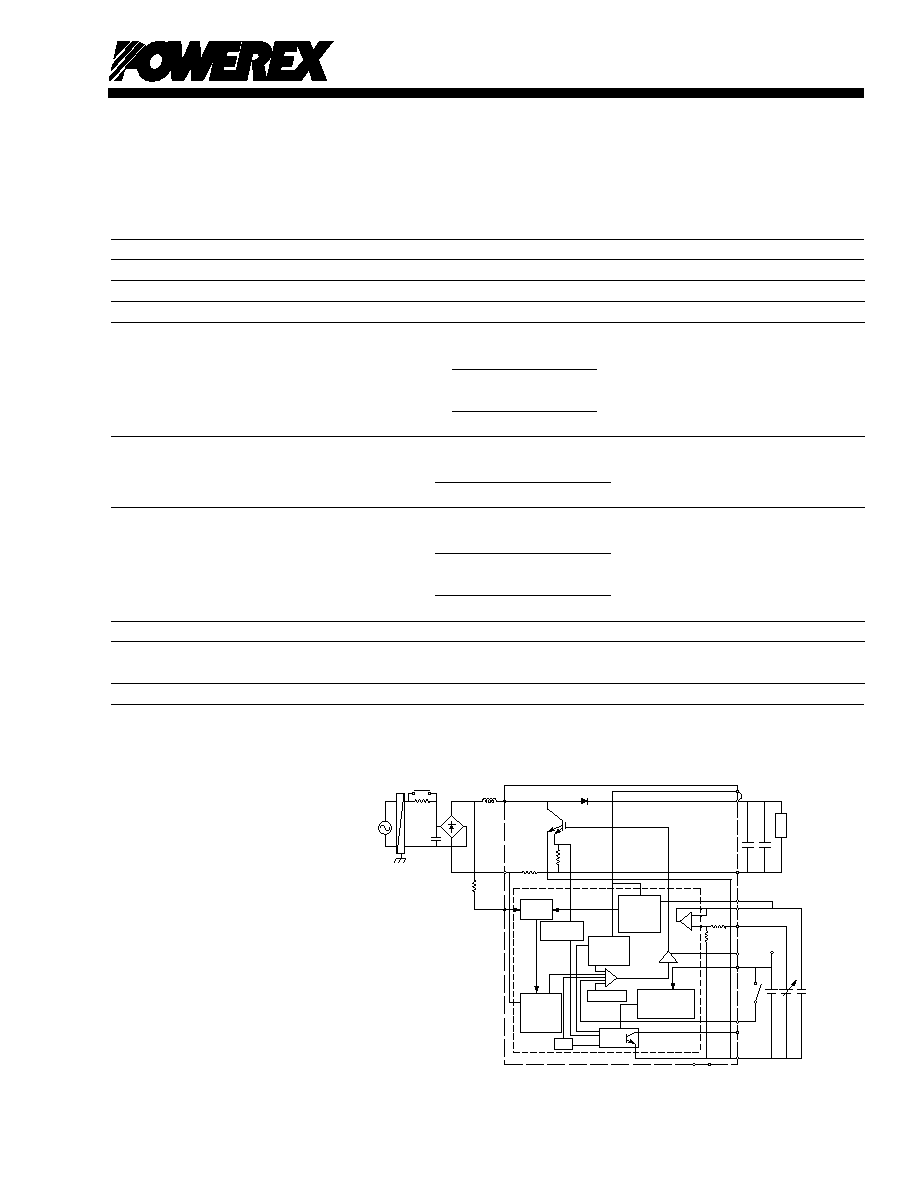
Internal Function Block Diagram
Note 1:
When applying 200V class input voltage,
please use In-rush current limitter S and R
for stable and safe operation.
Note 2:
Selection of R
v
:
When applying 200V class Input Voltage,
please use 270k
, 0.25W.
When applying 100V input voltage please
use R
v
= 0
(short).
Note 3:
Please make sure to short between V
O
and
P2 terminals for stable and safe operation.

PM52AUBW060
IntellimodTM Module
Active Filter IPM
20 Amperes/600 Volts
4
Powerex, Inc., 200 Hillis Street, Youngwood, Pennsylvania 15697-1800 (724) 925-7272
Control Sector
Supply Voltage
V
D
Applied between V
D
-GND
13.5
15
16.5
Volts
Circuit Current (Active)
I
D
≠
25
30
mA
Circuit Current
I
D
≠
13
≠
mA
Input ON Threshold Voltage
V
th(on)
≠
2.75
3.3
Volts
Input OFF Threshold Voltage
V
th(off)
1.9
2.45
≠
Volts
Switching Frequency
f
SW
18
20
22
kHz
Supply Circuit Under Voltage Protection
U
V
Trip Level (Note 2)
11.5
12.0
12.5
Volts
U
VR
Reset Level (Note 2)
12.0
12.5
13.0
Volts
V
ctrl
Current
I
ctrl
V
O
= 300V, V
D
= 15V, V
ctrl
= 1.04V
≠
-0.31
≠
mA
Output Voltage Protection
OV
1
Trip Level (Note 2)
V
O
+10
V
O
+20
V
O
+30
Volts
OV
1R
Reset Level (Note 2)
OV1-9
OV1-7
OV1-5
Volts
Over Voltage Protection
OV
2
Trip Level (Note 2)
400
415
430
Volts
Short Circuit Current Trip Level
SC
Trip Level (Note 2)
≠
150
≠
A
Over Temperature Protection
OT
Trip Level (Note 2)
100
110
120
∞
C
OT
R
Reset Level (Note 2)
≠
90
≠
∞
C
Fault Output Voltage
V
FOH
I
FOL
20
µ
A (Non-operating)
4.5
≠
≠
Volts
V
FOL
I
FOL
10mA (Operating)
≠
≠
1.0
Volts
Note 2:
Fault output is given when the internal UV protection (Auto-reset)
Fault output is not given when the internal OV1 protection (Auto-reset)
Fault output is given when the internal OV2 protection (Reset when ON/OFF [terminal 13] is low)
Fault output is given when the internal SC protection (Reset when ON/OFF [terminal 13] is low)
Fault output is given when the internal OT protection (Auto-reset)

5
PM52AUBW060
IntellimodTM Module
Active Filter IPM
20 Amperes/600 Volts
Powerex, Inc., 200 Hillis Street, Youngwood, Pennsylvania 15697-1800 (724) 925-7272
Electrical Characteristics,
(T
j
= 25
∞
C, V
D
= 15V, L1 = 1mH, C
O
= 1mF unless otherwise noted)
Characteristics
Symbol
Test Conditions
Min.
Typ.
Max.
Units
IGBT Sector
Inductive Load Switching Times
t
C(on)
V
CE
= 300V, I
CE
= 30A,
≠
0.07
≠
µ
S
t
C(off)
T
j
= 125
∞
C
≠
0.24
≠
µ
S
t
rr
V
CE
= 300V, I
F
= 30A, T
j
= 125
∞
C
≠
0.07
≠
µ
S
Collector-Emitter Saturation Voltage
V
CE(sat)
I
CE
= 50A
≠
1.8
2.4
Volts
Diode Forward Voltage
V
EC
I
E
= 50A
≠
2.1
2.6
Volts
Collector-Emitter Cutoff Current
I
CES
V
CE
= 600V
≠
≠
1.0
mA
Repetitive Peak Reverse Current
I
RRM
V
RRM
= 600V
≠
≠
1.0
mA
Reverse Recovery Current
I
rr
V
CE
= 300V, I
CE
= 30A
≠
45
≠
A
Thermal Characteristics
Characteristic
Symbol
Condition
Min.
Typ.
Max.
Units
Junction to Case Thermal Resistance
R
th(j-c)
IGBT
≠
≠
0.94
∞
C/Watt
R
th(j-c)
FWDi
≠
≠
1.15
∞
C/Watt
Contact Thermal Resistance
R
th(c-f)
Case to Fin Per Module,
≠
≠
0.09
∞
C/Watt
Thermal Grease Applied
Recommended Conditions for Use
Characteristic
Symbol
Condition
Min.
Typ.
Max.
Units
Supply Voltage
V
i
Applied between P
1
-N
1
90
≠
255
V
rms
V
D
Applied between V
D
-GND
13.5
15
16.5
Volts
Input Current
I
i
≠
≠
20
Arms
Output Voltage
V
O
170
300
350
Volts
Load
V
i
= 100V, V
O
= 300V
100
≠
2000
Watts
Reactor
L
≠
1
≠
mF
Input Capacitor
C
i
≠
3.3
≠
µ
F
Output Capacitor
C
O
1000
≠
≠
µ
F
C
O
'
≠
3.3
≠
µ
F