QIS0660001
Powerex Inc., 200 Hillis St., Youngwood, PA 15697 (724) 925-7272
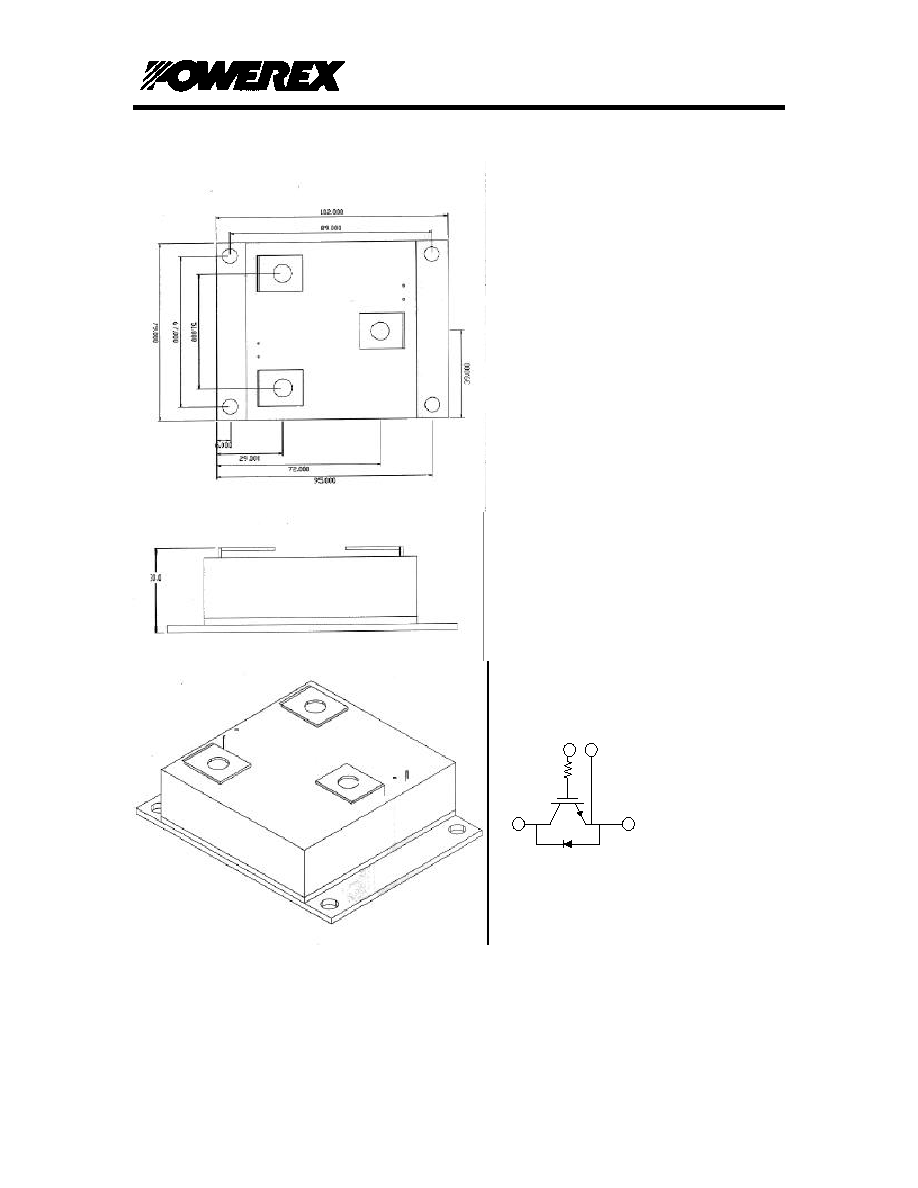
Single IGBT H-Series
Hermetic Module
600 Amperes/600 Volts
Page 1
PRELIMINARY
05/30/97
Description:
Powerex IGBT Hermetic modules are
designed for use in switching applications.
Each Module consists of two IGBT transistors
in a half bridge configuration with each
transistor having a reverse connected super
fast recovery free wheel diode. All
components are located in a hermetically
sealed chamber and are electrically isolated
from the heat sinking base plate, offering
simplified system assembly and thermal
management.
Features:
Low Drive Power
Low V
CE(sat)
Discrete Super-Fast Recovery
(70ns) Free-Wheel Diode
High Frequency Operation (20-
25kHz)
Isolated Base plate for Easy Heat
sinking
Fully Hermetic Package
Package Design Capable of Use at
High Altitudes
Package can be modified to adhere
to customer dimensions.
Schematic:
Applications:
AC Motor Control
Motion/Servo Control
Air Craft Applications
Ordering Information:
Contact Powerex Custom Modules
QIS0660001
Powerex Inc., 200 Hillis St., Youngwood, PA 15697 (724) 925-7272
Single IGBT H-Series
Hermetic Module
600 Amperes/600 Volts
Page 2
PRELIMINARY
05/30/97
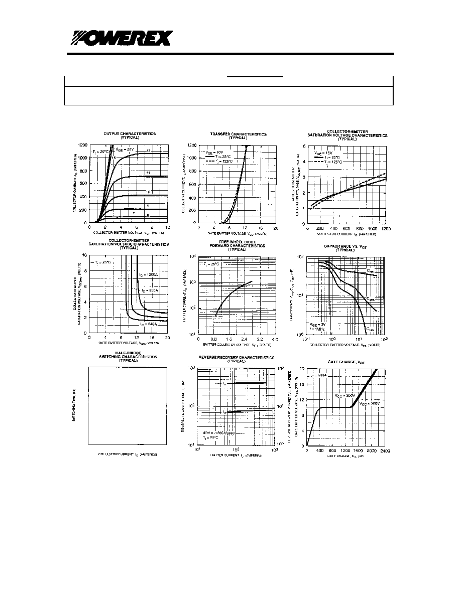
Maximum Ratings, Tj=25
∞
∞
C unless otherwise specified
Ratings
Symbol
Units
Collector Emitter Voltage
V
CES
600
Volts
Gate Emitter Voltage
V
GES
±
20
Volts
Collector Current
I
C
600
Amperes
Peak Collector Current
I
CM
1200*
Amperes
Diode Forward Current
I
FM
600
Amperes
Diode Forward Surge Current
I
FM
1200*
Amperes
Power Dissipation
P
d
2100
Watts
V Isolation
V
RMS
2500
Volts
Static Electrical Characteristics, Tj=25
∞
∞
C unless otherwise specified
Characteristic
Symbol
Test
Conditions
Min
Typ
Max
Units
Collector Cutoff Current
I
CES
V
CE
=V
CES
1.0
mA
Gate Leakage Current
I
GES
V
CE
=0V
0.5
µ
A
Gate-Emitter Threshold Voltage
V
GE(th)
I
C
=60mA,
V
CE
=10V
4.5
6.0
7.5
Volts
Collector-Emitter Saturation Voltage
V
CE(sat)
I
C
=600A,
V
GE
=15V
2.1
2.8
Volts
V
CE(sat)
I
C
=600A,
V
GE
=15V,
T
j
=150
∞
C
2.15
Volts
Total Gate Charge
Q
G
V
CC
=300V,
I
C
=600A,
V
GS
=15V
1800
nC
Diode Forward Voltage
V
FM
I
E
=600A,
V
GS
=0V
2.8
Volts
Dynamic Electrical Characteristics, Tj=25
∞
∞
C unless otherwise specified
Characteristic
Symbol
Test
Conditions
Min
Typ
Max
Units
Input Capacitance
C
ies
V
GE
=0V
60
nF
Output Capacitance
C
oes
V
CE
=10V
21
nF
Reverse Transfer Capacitance
C
res
f=1MHz
12
nF
Turn on Delay time
t
d(on)
V
CC
=300V
nS
Rise Time
t
r
I
C
=600A
nS
Turn off delay time
t
d(off)
V
GE1
=V
GE2
=15
V
nS
Fall Time
t
f
R
G
=1
300
nS
Diode Reverse Recovery Time
trr
I
E
=600A
110
nS
Diode reverse Recovery Charge
Qrr
di
E
/dt=
1200A/
µ
S
1.62
µ
C
Thermal and Mechanical Characteristics, Tj=25
∞
∞
C unless otherwise specified
Characteristic
Symbol
Test
Conditions
Min
Typ
Max
Units
Thermal Resistance, Junction to
R
JC
IGBT
0.06
∞
C/W
QIS0660001
Powerex Inc., 200 Hillis St., Youngwood, PA 15697 (724) 925-7272
Single IGBT H-Series
Hermetic Module
600 Amperes/600 Volts
Page 3
PRELIMINARY
05/30/97
Case
Thermal Resistance, Junction to
Case
R
JC
Diode
0.12
∞
C/W