TBK0
Phase Control Thyristor
Powerex, Inc., 200 Hillis Street, Youngwood, Pennsylvania 15697-1800 (724)925-7272
1250 Amperes 6500 Volts
FEATURES:
Low On-State Voltage
High di/dt Capability
High dv/dt Capability
Hermetic Ceramic Package
Excellent Surge and I
2
t Ratings
APPLICATIONS:
DC Power Supplies
ORDERING INFORMATION
Motor Controls
AC Soft-Starters
Select the complete 12 digit Part Number using the table below.
EXAMPLE: TBK0651203DH is a 6500V-1200A SCR with 200ma
IGT and 12 inch gate and cathode potential leads.
PART
Voltage
Rating
Voltage
Code
Current
Rating
Current
Code
Turn-Off
Gate
Leads
V
DRM
-V
RRM
I
tavg
Tq
I
GT
TBK0
6500
65
1250
12
0
3
6200
62
6000
60
500us
200ma
12"
(typ.)
(max)
Revised:
6/25/2002
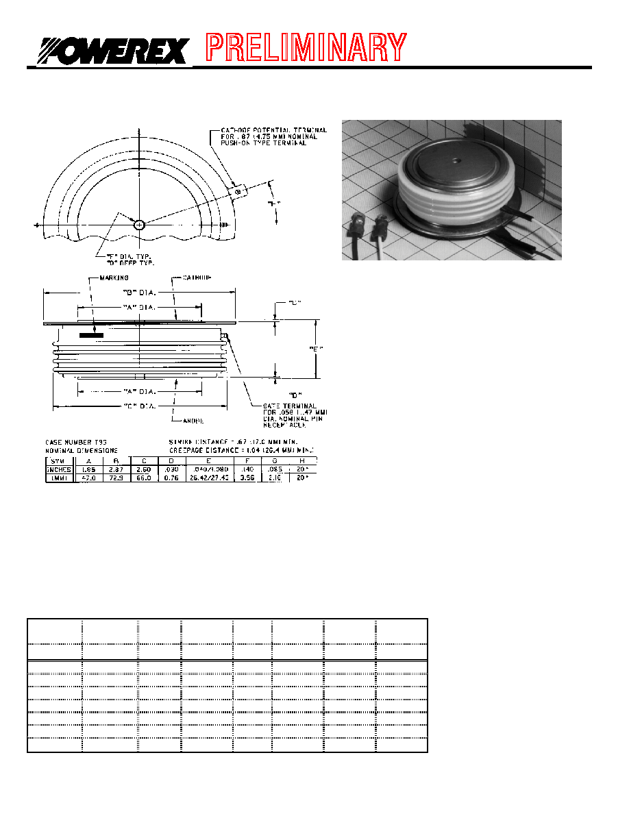
The TBK0 is a high voltage, high current
disc pack SCR employing a high di/dt
gate structure. This gate design allows
the SCR to be reliably operated at high
di/dt and dv/dt conditions in various
phase control applications.
Page 1

TBK0
Phase Control Thyristor
Powerex, Inc., 200 Hillis Street, Youngwood, Pennsylvania 15697-1800 (724)925-7272
1250 Amperes 6500 Volts
Absolute Maximum Ratings
Characteristic
Symbol
Rating
Units
Repetitive Peak Voltage
V
DRM
-V
RRM
6500
Volts
Average On-State Current, T
C
=70∞C
I
T(Avg.)
1250
A
RMS On-State Current, T
C
=70∞C
I
T(RMS)
1963
A
Average On-State Current, T
C
=50∞C
I
T(Avg.)
1500
A
RMS On-State Current, T
C
=50∞C
I
T(RMS)
2356
A
Peak One Cycle Surge Current, 60Hz, V
R
=0V
I
TSM
22,000
A
Peak One Cycle Surge Current, 50Hz, V
R
=0V
I
TSM
20,742
A
Fuse Coordination I
2
t, 60Hz
I
2
t
2.02E+06
A
2
s
Fuse Coordination I
2
t, 50Hz
I
2
t
2.15E+06
A
2
s
Critical Rate-of-Rise of On-State Current
di/dt
100
A/us
Repetitive .67∑VDRM
Critical Rate-of-Rise of On-State Current
di/dt
200
A/us
Non-Repetitive .67∑VDRM
Peak Gate Power, 100us
P
GM
16
Watts
Average Gate Power
P
G(avg)
5
Watts
Operating Temperature
Tj
-40 to+125
∞C
Storage Temperature
T
Stg.
-50 to+150
∞C
Approximate Weight
3.5
lb
1.59
Kg
Mounting Force
9000-10000
lbs
40 - 44.5
KNewtons
Page 2

TBK0
Phase Control Thyristor
Powerex, Inc., 200 Hillis Street, Youngwood, Pennsylvania 15697-1800 (724)925-7272
1250 Amperes 6500 Volts
Electrical Characteristics,
Tj=25∞C unless otherwise specified
Rating
Characteristic
Symbol
Test Conditions
min
typ
max
Units
Repetitive Peak Forward
Leakage Current
I
DRM
Tj=125∞C, V
DRM
=Rated
200
ma
Repetitive Peak Reverse
Leakage Current
I
RRM
Tj=125∞C, V
RRM
=Rated
200
ma
Peak On-State Voltage
V
TM
Tj=25∞C, I
TM
=2000A
2.70
V
V
TM
Model, Low Level
V
0
Tj=125∞C
1.153
V
VTM = V
O
+
r∑
I
TM
r
15%
I
TM
- ∑I
TM
7.44E-04
V
TM
Model, High Level
V
0
Tj=125∞C
1.79
V
VTM = V
O
+
r∑
I
TM
r
∑I
TM
- I
TSM
5.60E-04
V
TM
Model, 4-Term
A
Tj=125∞C
0.00015
V
TM
= A + B∑Ln(I
TM
) +
B
15%I
TM
- I
TSM
0.184
C∑(I
TM
) + D∑(I
TM
)
Ω
C
0.000509
D
0.00634
Turn-On Delay Time
t
d
V
D
= 0.5∑V
DRM
2.5
us
Gate Drive: 40V - 20
Turn-Off Time
tq
Tj=125∞C
800
us
dv/dt = 20V/us to 80% V
DRM
dv/dt
(Crit)
dv/dt
Tj=125∞C Exp. Waveform
1000
V/us
V
D
=80% Rated
Gate Trigger Current
I
GT
Tj=25∞C V
D
= 12V
30
100
200
ma
Gate Trigger Voltage
V
GT
0.8
2.0
5.0
V
Peak Reverse Gate Voltage
V
GRM
5
V
Thermal Characteristics
Rating
Characteristic
Symbol
Test Conditions
min
typ
max
Units
Thermal Resistance
Junction to Case
R
jc
Double side cooled
0.0115
0.0125
∞C/Watt
Case to Sink
R
cs
Double side cooled
0.0015
0.002
∞C/Watt
Thermal Impedance Model
Z
jc
Double side cooled
Z
jc
(t) =
(A(
N
)∑(1-exp(-t/
Tau
(
N
))))
where:
N =
1
2
3
4
A(N
) =
1.10E-04
8.86E-04
4.54E-03
7.02E-03
T
au(N) =
5.05E-04
1.33E-02
1.95E-01
1.25E+00
Page 3

TBK0
Phase Control Thyristor
Powerex, Inc., 200 Hillis Street, Youngwood, Pennsylvania 15697-1800 (724)925-7272
1250 Amperes 6500 Volts
Maximum On-State Voltage Drop
0.0
2.0
4.0
6.0
8.0
10.0
100
1000
10000
100000
ITM (A)
VTM (
V
)
Tj = 125∞C
MAXIMUM TRANSIENT THERMAL
IMPEDANCE
0.00E+00
2.00E-03
4.00E-03
6.00E-03
8.00E-03
1.00E-02
1.20E-02
1.40E-02
0.001
0.01
0.1
1
10
Time (sec)
Therm
al Im
pedance
(∞
C/
Watt)
Maximum On-State Power Dissipation
0
1000
2000
3000
4000
5000
6000
0
500
1000
1500
2000
Iavg (A)
P
a
v
g
(W
a
tts
)
Sinusoidal Waveform
60∞
90∞
120∞
180∞
0∞
180∞
360∞
CONDUCTION ANGLE
Maximum Allowable Case Temperature
60
70
80
90
100
110
120
130
0
500
1000
1500
2000
Iavg (A)
Tc
(
∞
C
)
Sinusoidal Waveform
60∞
90∞
120∞
180∞
0∞
180∞
360∞
CONDUCTION ANGLE
Maximum On-State Power Dissipation
0
1000
2000
3000
4000
5000
6000
7000
0
500
1000
1500
2000
Iavg (A)
P
a
v
g
(W
a
tts
)
Square Waveform
60∞
90∞ 120∞
180∞
0∞
180∞
360∞
CONDUCTION ANGLE
360∞
Maximum Allowable Case Temperature
60
70
80
90
100
110
120
130
0
500
1000
1500
2000
Iavg (A)
Tc
(
∞
C
)
Square Waveform
60∞
90∞ 120∞ 180∞
0∞
180∞
360∞
CONDUCTION ANGLE
360∞
Page 4