59
Series 110...105 / 114...117 /
150...106
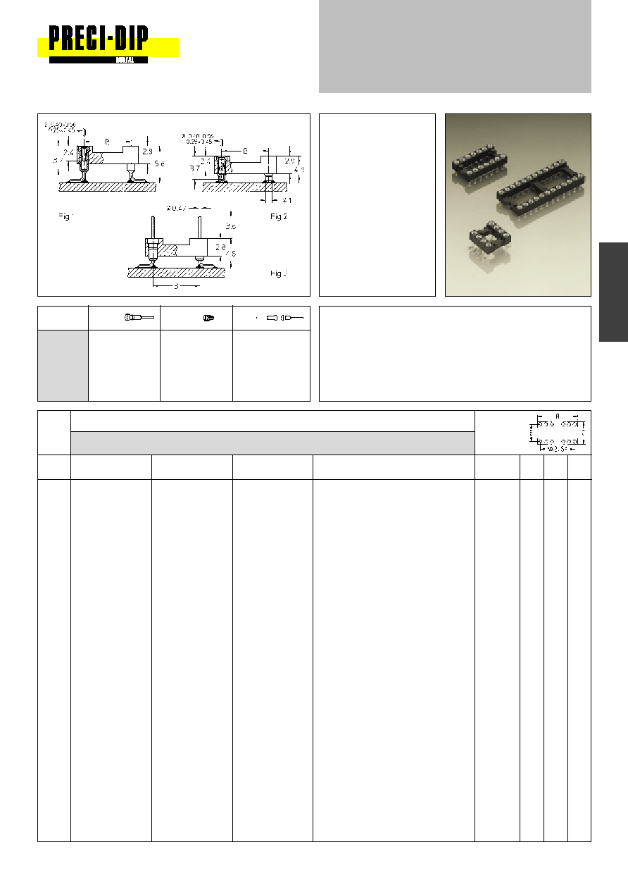
Dual-in-line sockets and headers
Open frame / surface mount
Specially designed for
reflow soldering including
vapor phase.
Insertion characteristics:
receptacle 4-finger
standard
New:
Pin connectors with
selective plated precision
screw machined pin,
plating code Z1.
Connecting side 1:
gold plated
soldering/PCB side 2:
tin plated
Platings
Sleeve
Clip
Pin
91
5
µ
m Sn Pb
0.25
µ
m Au
99
5
µ
m Sn Pb
5
µ
m Sn Pb
90
5
µ
m Sn Pb
Z1
1: 0.25
µ
m Au
2: 5
µ
m Sn Pb
Ordering information
Replace xx with required plating code. Other platings on request
Series 110-xx-xxx-41-105 and 150-xx-xxx-00-106 with gull wing
terminals for maximum strength and easy in-circuit test
Series 114-xx-xxx-41-117 with floating contacts compensate
effects of unevenly dispensed solder paste
10
110-xx-210-41-105
114-xx-210-41-117
150-xx-210-00-106
Fig. 1
12.6
5.08
7.6
4
110-xx-304-41-105
114-xx-304-41-117
150-xx-304-00-106
Fig. 2
5.0
7.62 10.1
6
110-xx-306-41-105
114-xx-306-41-117
150-xx-306-00-106
Fig. 3
7.6
7.62 10.1
8
110-xx-308-41-105
114-xx-308-41-117
150-xx-308-00-106
Fig. 4
10.1
7.62 10.1
10
110-xx-310-41-105
114-xx-310-41-117
150-xx-310-00-106
Fig. 5
12.6
7.62 10.1
14
110-xx-314-41-105
114-xx-314-41-117
150-xx-314-00-106
Fig. 6
17.7
7.62 10.1
16
110-xx-316-41-105
114-xx-316-41-117
150-xx-316-00-106
Fig. 7
20.3
7.62 10.1
18
110-xx-318-41-105
114-xx-318-41-117
150-xx-318-00-106
Fig. 8
22.8
7.62 10.1
20
110-xx-320-41-105
114-xx-320-41-117
150-xx-320-00-106
Fig. 9
25.3
7.62 10.1
22
110-xx-322-41-105
114-xx-322-41-117
150-xx-322-00-106
Fig. 10
27.8
7.62 10.1
24
110-xx-324-41-105
114-xx-324-41-117
150-xx-324-00-106
Fig. 11
30.4
7.62 10.18
28
110-xx-328-41-105
114-xx-328-41-117
150-xx-328-00-106
Fig. 12
35.5
7.62 10.1
22
110-xx-422-41-105
114-xx-422-41-117
150-xx-422-00-106
Fig. 13
27.8 10.16 12.6
24
110-xx-424-41-105
114-xx-424-41-117
150-xx-424-00-106
Fig. 14
30.4 10.16 12.6
28
110-xx-428-41-105
114-xx-428-41-117
150-xx-428-00-106
Fig. 15
35.5 10.16 12.6
32
110-xx-432-41-105
114-xx-432-41-117
150-xx-432-00-106
Fig. 16
40.6 10.16 12.6
24
110-xx-624-41-105
114-xx-624-41-117
150-xx-624-00-106
Fig. 17
30.4 15.24 17.7
28
110-xx-628-41-105
114-xx-628-41-117
150-xx-628-00-106
Fig. 18
35.5 15.24 17.7
32
110-xx-632-41-105
114-xx-632-41-117
150-xx-632-00-106
Fig. 19
40.6 15.24 17.7
36
110-xx-636-41-105
114-xx-636-41-117
150-xx-636-00-106
Fig. 20
45.7 15.24 17.7
40
110-xx-640-41-105
114-xx-640-41-117
150-xx-640-00-106
Fig. 21
50.6 15.24 17.7
42
110-xx-642-41-105
114-xx-642-41-117
150-xx-642-00-106
Fig. 22
53.2 15.24 17.7
48
110-xx-648-41-105
114-xx-648-41-117
150-xx-648-00-106
Fig. 23
60.9 15.24 17.7
No.
Order Codes
Insulator
of
dimen-
poles
Plating: see ordering information
sions
Fig. 1
Fig. 2
Fig. 3
See
A
B
C
page 50
For PCB Layout see page 60:
Fig. 4 Series 110 / 150,
Fig. 5 Series 114