 | –≠–ª–µ–∫—Ç—Ä–æ–Ω–Ω—ã–π –∫–æ–º–ø–æ–Ω–µ–Ω—Ç: 30KPA43CA | –°–∫–∞—á–∞—Ç—å:  PDF PDF  ZIP ZIP |
www.protekdevices.com
1
30KPA30A
thru
30KPA280A
POWER TVS COMPONENT
APPLICATIONS
Relay Drives
Motor (Start/Stop) Back EMF Protection
Module Lightning Protection
IEC COMPATIBILITY (EN61000-4)
61000-4-5 (Surge): 8/20µs - 95A, L4 (Line-Gnd), 167A, L3 (Power) & 48A, L4 (Line-Line)
FEATURES
30,000 Watts Peak Pulse Power per Line (10/1000µs)
Unidirectional & Bidirectional Configurations
Easy Mounting to Printed Circuit Boards
Available in Voltage Types Ranging From: 30V to 280V
MECHANICAL CHARACTERISTICS
Molded Case
Weight 2.5 grams (Approximate)
Flammability Rating UL 94V-0
Positive Terminal Marked with Band -
Unidirectional Devices
Marking: Logo & Part Number
AXIAL LEAD
05113.R7 9/02
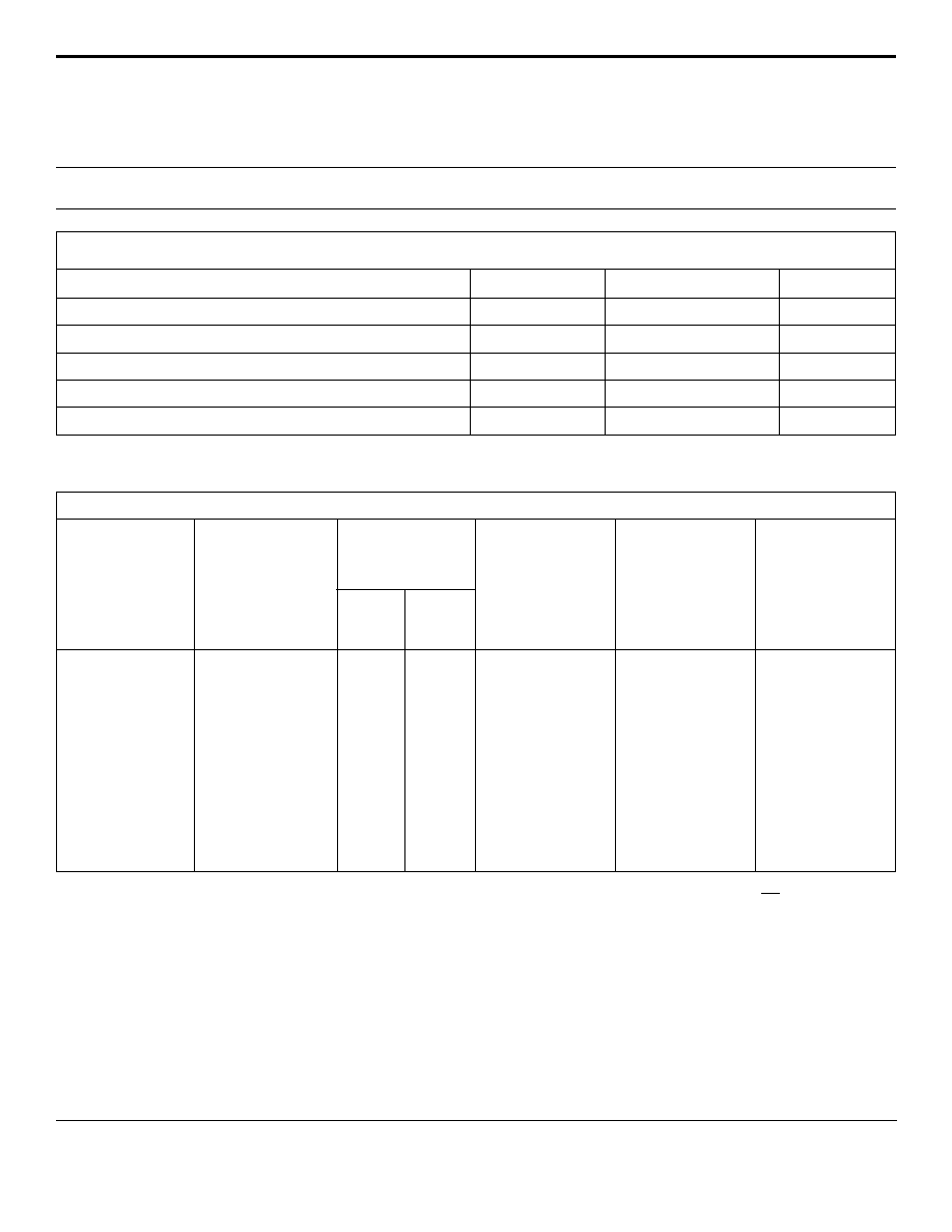
APPLICATION
V
CC
TYPICAL RELAY DRIVE PROTECTION
05113
. . . engineered solutions for the transient environmentTM
2
www.protekdevices.com
05113.R7 9/02
30KPA30A
thru
30KPA280A
DEVICE CHARACTERISTICS
MAXIMUM RATINGS @ 25∞C Unless Otherwise Specified
Peak Pulse Power Dissipation (t
p
=10/1000µs) - See Fig. 1
Forward Surge Rating (1/20 seconds) - See Note 2
SYMBOL
VALUE
Amps
200
Watts
UNITS
30,000
I
F
P
PP
PARAMETER
ELECTRICAL CHARACTERISTICS
PART
NUMBER
(Notes 1 & 2)
RATED
STAND-OFF
VOLTAGE
V
WM
VOLTS
BREAKDOWN
VOLTAGE
MAXIMUM
CLAMPING
VOLTAGE
(See Fig. 2)
@ 10/1000µs
V
C
@ I
PP
TEMPERATURE
COEFFICIENT
OF V
(BR)
V
(BR)
mV/∞C
30KPA30A
30KPA36A
30KPA43A
30KPA48A
30KPA64A
30KPA70A
30KPA75A
30KPA90A
30KPA160A
30KPA180A
30KPA260A
30KPA280A
30.0
36.0
43.0
48.0
64.0
70.0
75.0
90.0
160.0
180.0
260.0
280.0
33.3
40.0
47.8
53.3
71.1
77.8
83.3
100.0
178.0
200.0
289.0
311.0
55.2V @ 543.0A
61.8V @ 485.0A
73.0V @ 410.0A
77.4V @ 388.0A
104.0V @ 294.0A
109.0V @ 274.0A
119.4V @ 251.0A
147.0V @ 206.0A
252.6V @ 119.0A
291 @ 104A
416.0V @ 72.0A
464.0V @ 65.0A
5000
2000
1000
250
10
10
10
10
10
10
10
10
MAXIMUM
LEAKAGE
CURRENT
@V
WM
I
D
µA
34
41
50
56
76
83
89
109
195
230
317
342
Note 1: Part numbers shown are unidirectional devices. Add a "CA" suffix to specify bidirectional devices, such as 30KPA30CA.
Devices shown
are preferred voltages. Contact factory for additional voltages.
Note 2: V
F
= 15 Volts @ 200A, 8.3ms (1/2 Sine Wave) -
unidirectional devices only.
MIN
V
(BR)
VOLTS
@I
T
mA
50
50
50
5
5
5
5
5
5
5
5
5
1.0
Watts
P
D
Steady State Power Dissipation
-55 to +150
0
C
Storage Temperature
-55 to +150
0
C
T
J
Operating Temperature
T
STG
3
www.protekdevices.com
05113.R7 9/02
30KPA30A
thru
30KPA280A
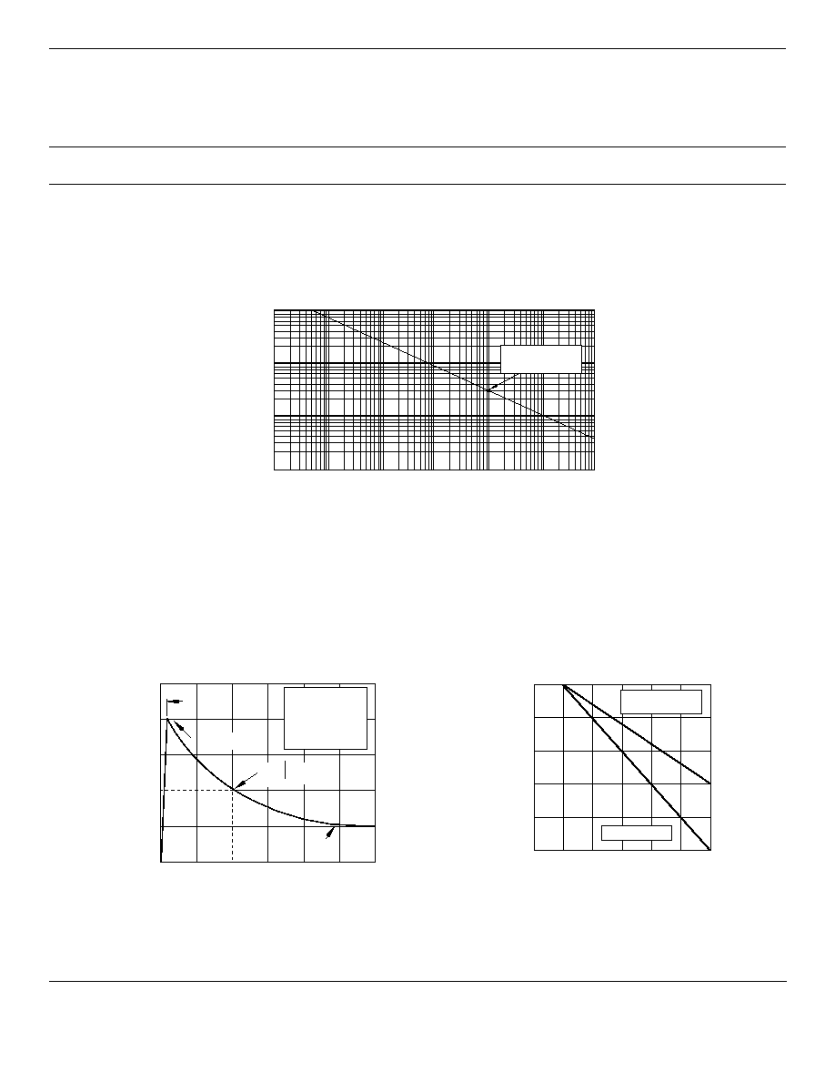
GRAPHS
0 1 2 3
t - Time - ms
0
50
100
I
PP
- Peak Pulse Current - % of I
PP
TEST
WAVEFORM
PARAMETERS
t
f
= 10µs
t
d
= 1,000µs
t
f
Peak Value I
PP
e
-t
FIGURE 2
PULSE WAVE FORM
t
d
= t
I
PP
/2
0 25 50 75 100 125 150
T
L
- Lead Temperature - ∞C
20
40
60
80
100
% Of Rated Power
Peak Pulse Power
10/1000µs
Average Power
FIGURE 3
POWER DERATING CURVE
0
0.1 1 10 100 1,000 10,000 100,000
t
d
- Pulse Duration - µs
0
10
100
1,000
P
PP
- Peak Pulse Power - kilowatts
FIGURE 1
PEAK PULSE POWER VS PULSE TIME
30kW 10/1000µs
Waveform

4
www.protekdevices.com
05113.R7 9/02
30KPA30A
thru
30KPA280A
COPYRIGHT © ProTek Devices 2002
SPECIFICATIONS: ProTek reserves the right to change the electrical and or mechanical characteristics described herein without notice (except JEDEC).
DESIGN CHANGES: ProTek reserves the right to discontinue product lines without notice, and that the final judgement concerning selection and specifications is the buyer's and that in furnishing engineering and
technical assistance, ProTek assumes no responsibility with respect to the selection or specifications of such products.
PACKAGE OUTLINE & DIMENSIONS
Protek Devices
2929 South Fair Lane, Tempe, AZ 85282
Tel: 602-431-8101 Fax: 602-431-2288
E-Mail: sales@protekdevices.com
Web Site: www.protekdevices.com
06028 Rev 0 - 12/01
NOTES:
1. Dimensions are exclusive of mold flash and metal
burrs.
A
B
C
D
E
-
9.10
-
1.30 DIA
9.10
1.00
0.34
1.00
0.048 DIA
0.34
-
0.36
-
0.052 DIA
0.36
24.5
8.60
24.5
1.20 DIA
8.60
DIM
MIN
MAX
MIN
MAX
MILLIMETERS
INCHES
PACKAGE DIMENSIONS
PACKAGE OUTLINE
30KPA
A
B
E
D
C