www.protekdevices.com
1
05053.R2 7/02
05053
. . . engineered solutions for the transient environment
420E212
thru
420E260
DUAL 4-20mA CONTROL LOOP PROTECTOR
APPLICATIONS
Security Alarm Systems
Industrial Control & Monitoring Systems
Remote Tech Site Station
Process Control Loops
IEC COMPATIBILITY (EN61000-4)
61000-4-2 (ESD): Air - 15kV, Contact - 8kV
61000-4-4 (EFT): 40A - 5/50ns
61000-4-5 (Surge): 8/20µs - 95A, Level 4(Line-Gnd) & 48A, Level 4(Line-Line)
FEATURES
Designed for 4-20mA Current Loops
Automatic Reset - Will Not Interrupt Service
Permanent Two-Stage Line Pair Protection
Line-to-Ground (Common) & Line-to-Line (Differential) Protection
Subnanosecond Response Time
Effective Against Lightning, Inductive Switching & ESD
MECHANICAL CHARACTERISTICS
Weight 50 grams (Approximate)
Flammability Rating UL 94V-0
Device Marking: Part Number, Date Code, Logo, and Terminal Designations
DESCRIPTION
The 420E2 series of protection is a two stage transient voltage protector providing primary and secondary protection against light-
ning, inductive switching and electrostatic discharge (ESD) transient threats. The first stage diverts the transient current through the
ground terminal return path and the second stage clamps the voltage to a safe level without interruption of service.
The 420E2 series is designed to protect 4-20mA analog control loops from differential and common mode transients. Terminals 1 and
2 are designed as the line pairs for both the line and equipment side of the protector. A transient voltage suppressor is internally
connected across each line pair for differential mode protection. Each line pair is referenced to ground.
This product can also be used on telephone, signal/data lines, security, timing and control interface circuits.
420E PACKAGE
www.protekdevices.com
2
05053.R2 7/02
420E212
thru
420E260
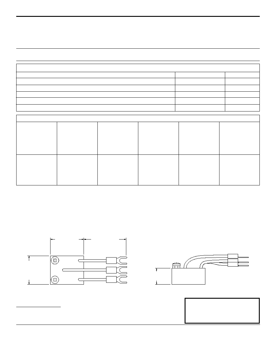
420E2 CASE OUTLINE
DEVICE CHARACTERISTICS
COPYRIGHT © ProTek Devices 2001
SPECIFICATIONS: ProTek reserves the right to change the electrical and or mechanical characteristics described herein without notice (except
JEDEC).
DESIGN CHANGES: ProTek reserves the right to discontinue product lines without notice, and that the final judgement concerning selection and
specifications is the buyer's and that in furnishing engineering and technical assistance, ProTek assumes no responsibility with respect to the
selection or specifications of such products.
ProTek Devices
2929 South Fair Lane, Tempe, AZ 85282
Tel: 602-431-8101 Fax: 602-431-2288
E-Mail: sales@protekdevices.com
Web Site: www.protekdevices.com
INSTALLATION INSTRUCTIONS
There are two (2) terminals on the LINE SIDE and three (3) wires on the EQUIPMENT SIDE of this surge protection device (SPD). The Ground
lead is considered ground for both the input terminal and the equipment wire connections. For the best results, the ground wire should be con-
nected to a low impedance ground or the green wire AC power ground. It is recommended that a #14 stranded wire be used for this connection.
Field (current) loops or incoming signal/data lines are to be cut or disconnected from the equipment to insert the 420E2 SPD. The LINE SIDE
terminals of the protector are to be connected to the field loop wires. The EQUIPMENT SIDE of the protector is connected to the equipment/
receiver/controller, etc. The location of the protector should be as close to the equipment requiring protection.
2.50" MAX
(63.5 mm)
1.40" MAX
(35.56 mm)
1.20" MAX
(30.48 mm)
0.675" MAX
(17.15 mm)
EQUIPMENT
SIDE
1
GND
2
1
2
LINE
SIDE
PROTEK
PART
NUMBER
MAXIMUM
OPERATING
LINE VOLTAGE
V
OP
± VOLTS
MAXIMUM
LEAKAGE
CURRENT
@ V
OP
I
D
µA
MAXIMUM
CLAMPING
VOLTAGE
(8/20µs)
@2,000A
V
C
VOLTS
MAXIMUM
CAPACITANCE
@ 0 V, 1 MHz
C
pF
MAXIMUM
LINE THRUPUT
RESISTANCE
R
OHMS
22
44
46
60
80
95
5.0
5.0
5.0
5.0
5.0
5.0
12.0
25.0
28.0
36.0
50.0
60.0
420E212
420E225
420E228
420E236
420E250
420E260
6000
3000
2800
1500
1200
1000
12
12
12
12
12
12
ELECTRICAL CHARACTERISTICS @ 25∫C Ambient Temperature
MAXIMUM RATINGS @ 25∞C Unless Otherwise Specified
VALUE
-55
∞
C to 100
∞
C
∞C
UNITS
PARAMETER
Storage Temperature
Operating Temperature
∞C
-55
∞
C to 100
∞
C
Operating Line Current
100
mA
Transient Source Voltage
6kV
V
10kA per line
A
Transient Current (8/20µs)
GND