
CPE 80
&
MB 80
1
05072.R2 1/03
www.protekdevices.com
MOTHERBOARD & ENCLOSURE
Only One Name Means ProTek'TionTM
APPLICATIONS
Multiple Data Line Panel Protection
Emergency Shutdown Systems
Process Control Panels
FEATURES
MB 80: Glass Filled Laminate Circuit Board with Stand-Offs
CPE 80: Rugged Cast Aluminum Two-Tone Baked Enamel Base &
Removable Cover
Wiring Interface Accepts a Maximum of Eight(8) Circuit Boards
Two 10-32 Brass Ground Studs for Low Impedance
Motherboard is Clearly Marked for Easy Installation
MECHANICAL CHARACTERISTICS
Screw Type Stripline Connectors for AWG 20-24 Wire
Four (4) Mounting Holes for #8 Screws
Approximate Weight of the MB 80: 340 grams
Approximate Weight of the CPE 80: 1.6 kilograms
Dimensions of the MB 80: 9"H (22.9 cm) x 5.5"W (14 cm), with 3" (7.6 cm)
Minimum Interface Depth if Mounting in an Enclosure
Dimensions of the CPE 80: 9.5"H (24.1 cm) x 6.25"W (15.8 cm), with 3.5"
(8.9 cm) Minimum Interface Depth if Mounting in an Enclosure
DESCRIPTION
The CPE 80 and MB 80 provides protection of 32 data lines using up to eight (8)
SPDs (surge protection device). These products accomodate a variety of SPDs
such as 232B, 422B and 420LB; which are not included with the motherboard
or enclosure. Available from ProTek Devices, each data line SPD has four, two
stage protection circuits. The SPDs provide primary and secondary protection
against lightning, inductive switching and ESD transient threats. The first stage
diverts the transient current through the ground terminal return part and the
second stage clamps the voltage to a safe level without interruption of service.
These interface board assemblies are located between the unprotected
transient threat environment (incoming data lines) and the protected sensitive
electronic equipment or system. The motherboard is marked identifying the
protected side. The unprotected side should be located away from the protected data line
cables.
The MB 80 is a motherboard containing eight (8) edge card connectors and two (2) strip
terminal blocks. The edge card connectors are soldered onto the motherboard, which is
connected to the terminal blocks by copper traces. The terminal blocks have screw type
connections for easy installation between the unprotected and the protected equipment.
Data line surge protection devices are inserted into the edge card connectors for protection
of sensitive equipment and/or systems.
The CPE 80 includes a motherboard (MB 80) inside a rugged, cast aluminum housing with
a removable cover. The housing contains two (2) holes on either side of the case for data
line cables. Mounting hardware is provided for the data line cables.
05072
MB 80 MOTHERBOARD
CPE 80 ENCLOSURE
2
www.protekdevices.com
05072.R2 1/03
CPE 80
&
MB 80
INSTALLATION INSTRUCTIONS
Maximum transient protection requires a good
ground system. This consists of a common
bonded or ground system, which interconnects AC
power and data line grounds. A single ground
connection is sufficient. However, it is more
important that the ground be a low impedance path
to the earth. A good earth connection is
necessary for lightning transient threat conditions.
Connections are usually best using a ground strap
where the cross-sectional area of the ground
connection is maximized. The ground connection
is made through the green AC power ground wire or
to a known earth ground system. If a ground wire
is used, it is recommended that it is a #14
stranded wire. A low impedence ground is
important to minimize a ground voltage potential
rise that may cause ground bounce within the
system or equipment.
MB 80 INSTALLATION INSTRUCTIONS
1. Select a suitable mounting location within 10
meters of the protected equipment. An enclosure
is recommended to protect against dust and
moisture.
2. Mount the board using the stand-offs and #8
screws provided.
3. Connect wires to appropriate terminals as show
in Figures 1 and 2. The ground wire MUST be kept
on the unprotected side of the board.
4. Insert protected boards. Be certain to insert
boards in the correct position as shown on the MB
80.
CPE 80 INSTALLATION INSTRUCTIONS
1. Select a suitable mounting location within 10
meters of the protected equipment.
2. Remove the cover and install retainer
assembly in holes. Do not tighten gland nut
bushing. See cable retainer assembly detail in
Figure 1.
3. Install base on a flat surface using #8 screws
provided.
4. Insert wires through cable retainer assemblies
and connect to appropriate terminals as shown in
Figures 1 and 2. The ground wire MUST enter the
enclosure ONLY through the unprotected side.
5. After completion of wiring, hand tighten gland
nut bushing.
6. Insert protector boards. Be certain to insert
boards in the correct position as shown on the
printed circuit board.
7. Replace cover and tighten cover mounting
screws.
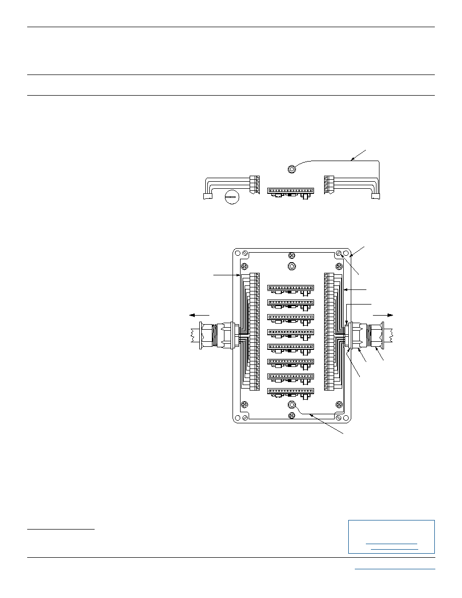
TYPICAL WIRING FORMAT FOR ONE 4 WIRE RS EIA
STANDARD DATA LINE PRODUCTS
Figure 1
Example of ProTek 15 pin protection board, such as 232B, 485B and TEL185B
2AP
4AP
3AP
Peripheral
Equipment
Connect to CPU or
PROTECTED SIDE
4FP
3FP
2FP
2GP
3GP
4GP
2HP
3HP
4HP
2CP
3CP
4CP
2DP
3DP
4DP
4EP
3EP
2EP
Peripheral
2AP
3AP
4AP
4BP
3BP
2BP
PROTECTED SIDE
Connect to CPU or
Equipment
PART NUMBER 31340-00001 - For use with Computer Data Line Protector Boards
GROUND LUG
Orient Board as Shown
Orient Board as Shown
Orient Board as Shown
1HP
4HU
3HU
2HU
1HU
4GU
3GU
2GU
2DU
Orient Board as Shown
Orient Board as Shown
Orient Board as Shown
1GP
1EP
1FP
1GU
2FU
3FU
4FU
1EU
2EU
3EU
4EU
4DU
3DU
1FU
Orient Board as Shown
Orient Board as Shown
1DP
1BP
1CP
1DU
4CU
3CU
2CU
1BU
2BU
3BU
4BU
4AU
3AU
1CU
Connect to
External
Data Lines
UNPROTECTED SIDE
1AP
R
2AU
1AU
GROUND LUG
Orient Board as Shown
Data Lines
External
Connect to
UNPROTECTED SIDE
1AP
1BP
1AU
2AU
1BU
3AU
4AU
GROUND LUG
To Common Equipment-Ground Point AWG 6-10
Wire
Cover Bolt
Mounting Screws
4 Wires per Data Line
Inside Mouting Nut
To Outside World
Data Line Cable
Gland Nut
Retaining Nut
Nylon Washer
To Common Equipment-Ground Point AWG 6-10 Wire
To Protected
Equipment
4 Wires per
Data Line
CPE & MB 80 WIRING CONFIGURATION
Figure 2
COPYRIGHT © ProTek Devices 2005
SPECIFICATIONS: ProTek reserves the right to change the electrical and or mechanical characteristics described herein without notice (except JEDEC).
DESIGN CHANGES: ProTek reserves the right to discontinue product lines without notice, and that the final judgement concerning selection and
specifications is the buyer's and that in furnishing engineering and technical assistance, ProTek assumes no responsibility with respect to the selection or
specifications of such products.
ProTek Devices
2929 South Fair Lane, Tempe, AZ 85282
Tel: 602-431-8101 Fax: 602-431-2288
E-Mail:
sales@protekdevices.com
Web Site:
www.protekdevices.com