 | –≠–ª–µ–∫—Ç—Ä–æ–Ω–Ω—ã–π –∫–æ–º–ø–æ–Ω–µ–Ω—Ç: EMC12F-LC | –°–∫–∞—á–∞—Ç—å:  PDF PDF  ZIP ZIP |
1
www.protekdevices.com
05087.R1 1/03
EMC3.3F-LC
thru
EMC15F-LC
TVS/LOW PASS L/C FILTER ARRAYS
APPLICATIONS
High-Speed Networks
Graphics/Video Cards
Global Positioning Systems
Wireless Networks
IEC COMPATIBILITY (EN61000-4)
61000-4-2 (ESD): Air - 15kV, Contact - 8kV
61000-4-4 (EFT): 40A - 5/50ns
FEATURES
300 Watts Peak Pulse Power per Line (tp=8/20µs)
EMI/RFI Low Pass Filtering
Very Low Insertion Loss: < 0.5dB up to 200 MHz
Excellent Matching Over the Operating Frequency
Protects 3.3 - 15 Volt I/O Ports
50 Ohm Network Terminations
L/C Bessel Filter
LOW CAPACITANCE: 10pF
MECHANICAL CHARACTERISTICS
Molded JEDEC SO-16WB (Wide Body) Package
Weight 0.15 grams (Approximate)
Flammability rating UL 94V-0
16mm Tape and Reel Per EIA Standard 481
Marking: Logo, Part Number & Pin One Defined By Dot on Top of Package
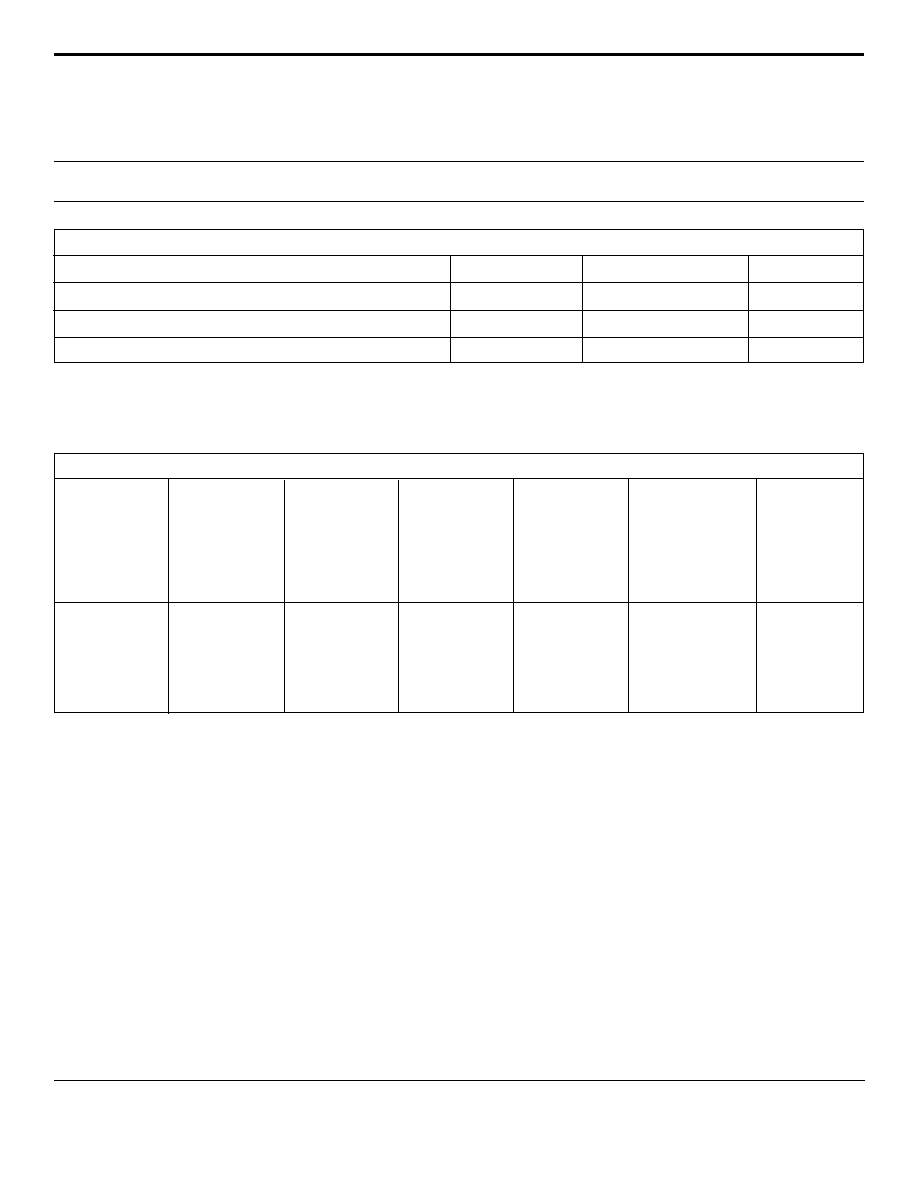
CIRCUIT DIAGRAM
SO-16WB
(Wide Body)
05087
. . . engineered solutions for the transient environmentTM
1
16
15
14
13
12
11
10
9
2
3
4
5
6
7
8
GND
GND
GND
GND
GND
GND
GND
GND
OUT
OUT
OUT
OUT
IN
IN
IN
IN
2
www.protekdevices.com
EMC3.3F-LC
thru
EMC15F-LC
05087.R1 1/03
DEVICE CHARACTERISTICS
MAXIMUM RATINGS @ 25∞C Unless Otherwise Specified
Operating Temperature
SYMBOL
VALUE
-55
∞
C to 150
∞
C
∞C
∞C
-55
∞
C to 150
∞
C
UNITS
T
J
T
STG
PARAMETER
Storage Temperature
Peak Pulse Power (t
p
= 8/20µs) - See Figure 1
P
PP
300
Watts
ELECTRICAL CHARACTERISTICS PER LINE @ 25∞C Unless Otherwise Specified
PART
NUMBER
MAXIMUM
OPERATING
VOLTAGE
V
(OP)
VOLTS
MINIMUM
BREAKDOWN
VOLTAGE
(See Note 1)
@ 1mA
V
(BR)
VOLTS
MAXIMUM
CLAMPING
VOLTAGE
(See Fig. 5)
@ I
PP
= 5A
V
C
VOLTS
CUT-OFF
FREQUENCY
@ -3dB
f
c
MHz
EMC3.3F-LC
EMC5.0F-LC
EMC8.0F-LC
EMC12F-LC
EMC15F-LC
3.3
5.0
8.0
12.0
15.0
4.0
6.0
8.5
13.3
16.7
100
50
5
5
5
9.0
11.0
16.6
24.0
30.0
MAXIMUM
LEAKAGE
CURRENT
(See Note 1)
@V
WM
I
D
µA
TYPICAL
CAPACITANCE
(See Note 2)
@ 0V, 1 MHz
C
pF
10
10
10
10
10
500
500
500
500
500
Note 1:
Apply positive (negative) potential between input pins to ground pins, output open.
Note 2:
Measure capacitance between output pins to ground pins.

3
www.protekdevices.com
05087.R1 1/03
EMC3.3F-LC
thru
EMC15F-LC
GRAPHS
0 25 50 75 100 125 150
T
L
- Lead Temperature - ∞C
20
40
60
80
100
% Of Rated Power
Peak Pulse Power
8/20µs
Average Power
FIGURE 3
POWER DERATING CURVE
0
0 5 10 15 20 25 30
t - Time - µs
0
20
40
60
80
100
120
I
PP
- Peak Pulse Current - % of I
PP
TEST
WAVEFORM
PARAMETERS
t
f
= 8µs
t
d
= 20µs
t
f
Peak Value I
PP
e
-t
t
d
= t
I
PP
/2
FIGURE 2
PULSE WAVE FORM
0.1 1 10 100 1,000 10,000
t
d
- Pulse Duration - µs
300W 8/20µs Waveform
10
100
1,000
10,000
P
PP
- Peak Pulse Power - Watts
FIGURE 1
PEAK PULSE POWER VS PULSE TIME

4
www.protekdevices.com
EMC3.3F-LC
thru
EMC15F-LC
05087.R1 1/03
COPYRIGHT © ProTek Devices 2003
SPECIFICATIONS: ProTek reserves the right to change the electrical and or mechanical characteristics described herein without notice (except JEDEC).
DESIGN CHANGES: ProTek reserves the right to discontinue product lines without notice, and that the final judgement concerning selection and specifications is the buyer's and that in furnishing engineering and
technical assistance, ProTek assumes no responsibility with respect to the selection or specifications of such products.
PACKAGE OUTLINE & DIMENSIONS
ProTek Devices
2929 South Fair Lane, Tempe, AZ 85282
Tel: 602-431-8101 Fax: 602-431-2288
E-Mail: sales@protekdevices.com
Web Site: www.protekdevices.com
PART NUMBER SUFFIXES USED FOR TAPE & REEL/BULK ORDERING:
Surface mount product is taped and reeled in accordance with EIA-481.
Suffix-T13 = 13 Inch Reel - 2,500 pieces per reel i.e: EMC5.0-LC-T13
No Suffix = Product Shipped in Tubes of 46 pcs per Tube
A
B
C
D
F
G
J
K
P
R
10.45
7.60
2.65
0.49
0.90
1.27 BSC
0.32
0.25
10.55
0.75
0.400
0.292
0.093
0.014
0.020
0.05 BSC
0.010
0.004
0.395
0.010
0.411
0.299
0.104
0.019
0.035
0.05 BSC
0.012
0.009
0.415
0.029
10.15
7.40
2.35
0.35
0.50
1.27 BSC
0.25
0.10
10.05
0.25
DIM
MIN
MAX
MIN
MAX
MILLIMETERS
INCHES
PACKAGE DIMENSIONS
NOTES:
1. - T - = Seating Plane and Datum Surface.
2. Dimensions "A" and "B" are Datum.
3. Dimensions "A" and "B" do not include mold
protrusions.
4. Maximum mold protrusion is 0.015" (0.380 mm)
per side.
5. Dimensioning and tolerances per ANSI Y14.5M,
1982.
6. Dimensions are exclusive of mold flash and metal
burrs.
PACKAGE OUTLINE
SO-16
(Wide Body)
MOUNTING PAD
M
-A-
-B- P
D
G
-T-
K
C
J
R X 45
∫
F
0.010" (0.25 MM)
M
B
M
8 PL
0.010" (0.25 MM)
S
B
M
16 PL
T
A
S
16
9
8
1
0.050" TYP
0.030"
±
0.005"
0.420" MIN
0.325"
±
0.005"
0.045"
±
0.005"
0
∫
- 7
∫
06008 Rev 1 - 11/01