 | –≠–ª–µ–∫—Ç—Ä–æ–Ω–Ω—ã–π –∫–æ–º–ø–æ–Ω–µ–Ω—Ç: SM8LC | –°–∫–∞—á–∞—Ç—å:  PDF PDF  ZIP ZIP |
1
www.protekdevices.com
05019.R2 5/02
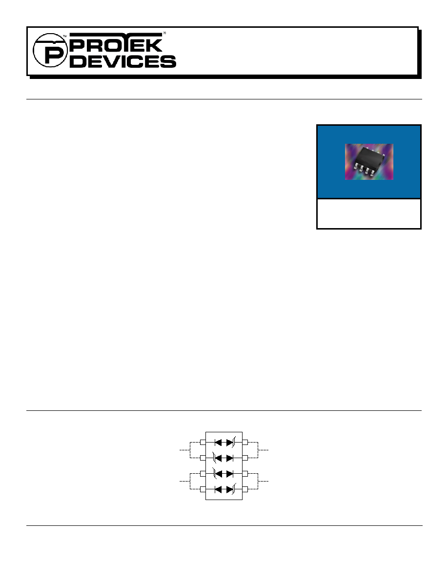
HIGH SPEED TVS DIODE ARRAY
APPLICATIONS
Video-on-Demand
ISDN Telecom Interface
USB, ADSL & SCSI Interface
Modems
LAN Interconnects
Portable Electronics
IEC COMPATIBILITY (EN61000-4)
61000-4-2 (ESD): Air - 15kV, Contact - 8kV
61000-4-4 (EFT): 40A - 5/50ns
61000-4-5 (Surge): 24A, 8/20µs - Level 2(Line-Gnd) & Level 3(Line-Line)
FEATURES
800 Watts Peak Pulse Power Dissipation per Line Pair (t
p
= 8/20µs)
Two Line Pairs Protection per Package
Available in 5 Voltage Types Ranging from 5.0V to 24V
Bidirectional Configuration
LOW CAPACITANCE 25 pF
MECHANICAL CHARACTERISTICS
Molded JEDEC SO-8
Weight 0.1 gram (Approximate)
Flammability Rating UL 94V-0
12mm Tape and Reel Per EIA Standard 481
Device Marking: Marking Code & Logo
Pin 1 Indicated By Dot on Top of Package
SO-8
05019
. . . engineered solutions for the transient environmentTM
SM8LC05
thru
SM8LC24
1
2
4
7
6
5
3
8
CIRCUIT DIAGRAM
2
www.protekdevices.com
05019.R2 5/02
SM8LC05
thru
SM8LC24
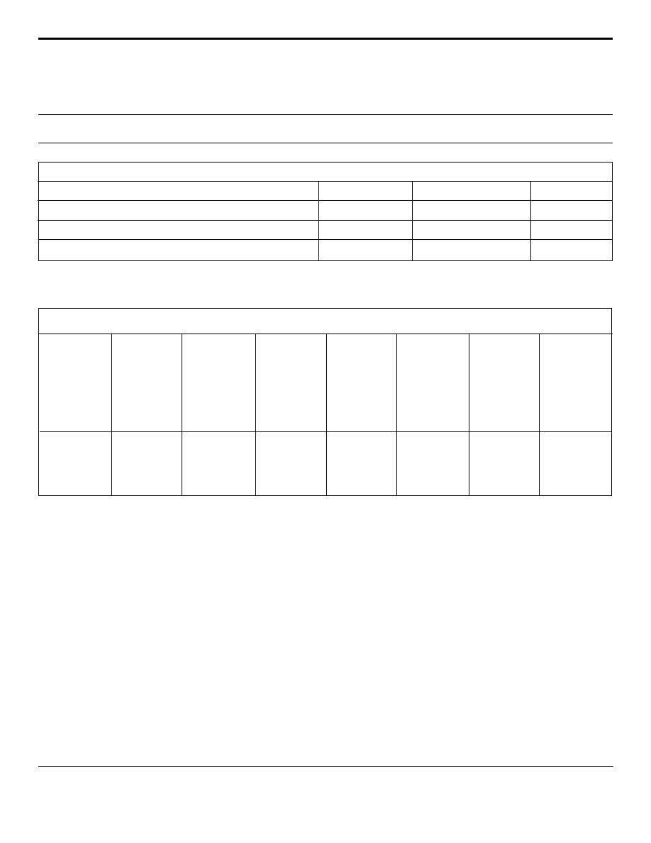
DEVICE CHARACTERISTICS
MAXIMUM RATINGS @ 25∞C Unless Otherwise Specified
Operating Temperature
SYMBOL
VALUE
-55
∞
C to 150
∞
C
∞C
∞C
-55
∞
C to 150
∞
C
UNITS
T
J
T
STG
PARAMETER
Storage Temperature
Peak Pulse Power (t
p
= 8/20µs) - See Figure 1
P
PP
800
Watts
Note 1:
Devices are designed to be used in parallel (See Circuit Diagram) Page 1. For other applications, contact the factory. Do not surge in the
"forward" direction of the TVS.
Note 2:
Do not surge from pins 1 to 8, 7 to 2, 6 to 3 and 4 to 5. PIV typically greater than 100 volts for each rectifier diode.
ELECTRICAL CHARACTERISTICS PER LINE @ 25∞C Unless Otherwise Specified
PART
NUMBER
(See Note 1)
DEVICE
MARKING
MINIMUM
BREAKDOWN
VOLTAGE
@ 1mA
V
(BR)
VOLTS
MAXIMUM
CLAMPING
VOLTAGE
(See Fig. 2)
@ I
P
= 1A
V
C
VOLTS
MAXIMUM
CLAMPING
VOLTAGE
(See Fig. 2)
@8/20µs
V
C
@ I
PP
MAXIMUM
CAPACITANCE
0V @ 1 MHz
C
pF
SM8LC05
SM8LC08
SM8LC12
SM8LC15
SM8LC24
PGA
PGB
PGC
PGD
PGE
6.0
8.5
13.3
16.7
26.7
9.8
13.3
19.0
25.5
40.0
24.6V @ 45A
25.5V @ 40A
32.9V @ 34A
38.5V @ 27A
48.5V @ 22A
25
25
25
25
25
MAXIMUM
LEAKAGE
CURRENT
@V
WM
I
D
µA
100
10
4
4
4
RATED
STAND-OFF
VOLTAGE
V
WM
VOLTS
5.0
8.0
12.0
15.0
24.0

3
www.protekdevices.com
05019.R2 5/02
SM8LC05
thru
SM8LC24
GRAPHS
0 25 50 75 100 125 150
T
L
- Lead Temperature - ∞C
20
40
60
80
100
% Of Rated Power
Peak Pulse Power
8/20µs
Average Power
FIGURE 3
POWER DERATING CURVE
0
0.01 1 10 100 1,000 10,000
t
d
- Pulse Duration - µs
10
100
1,000
10,000
P
PP
- Peak Pulse Power - Watts
FIGURE 1
PEAK PULSE POWER VS PULSE TIME
0 5 10 15 20 25 30
t - Time - µs
0
20
40
60
80
100
120
I
PP
- Peak Pulse Current - % of I
PP
TEST
WAVEFORM
PARAMETERS
t
f
= 8µs
t
d
= 20µs
t
f
Peak Value I
PP
e
-t
FIGURE 2
PULSE WAVE FORM
800W, 8/20µs Waveform
I
PP
/2
t
d
= t
4
www.protekdevices.com
05019.R2 5/02
SM8LC05
thru
SM8LC24
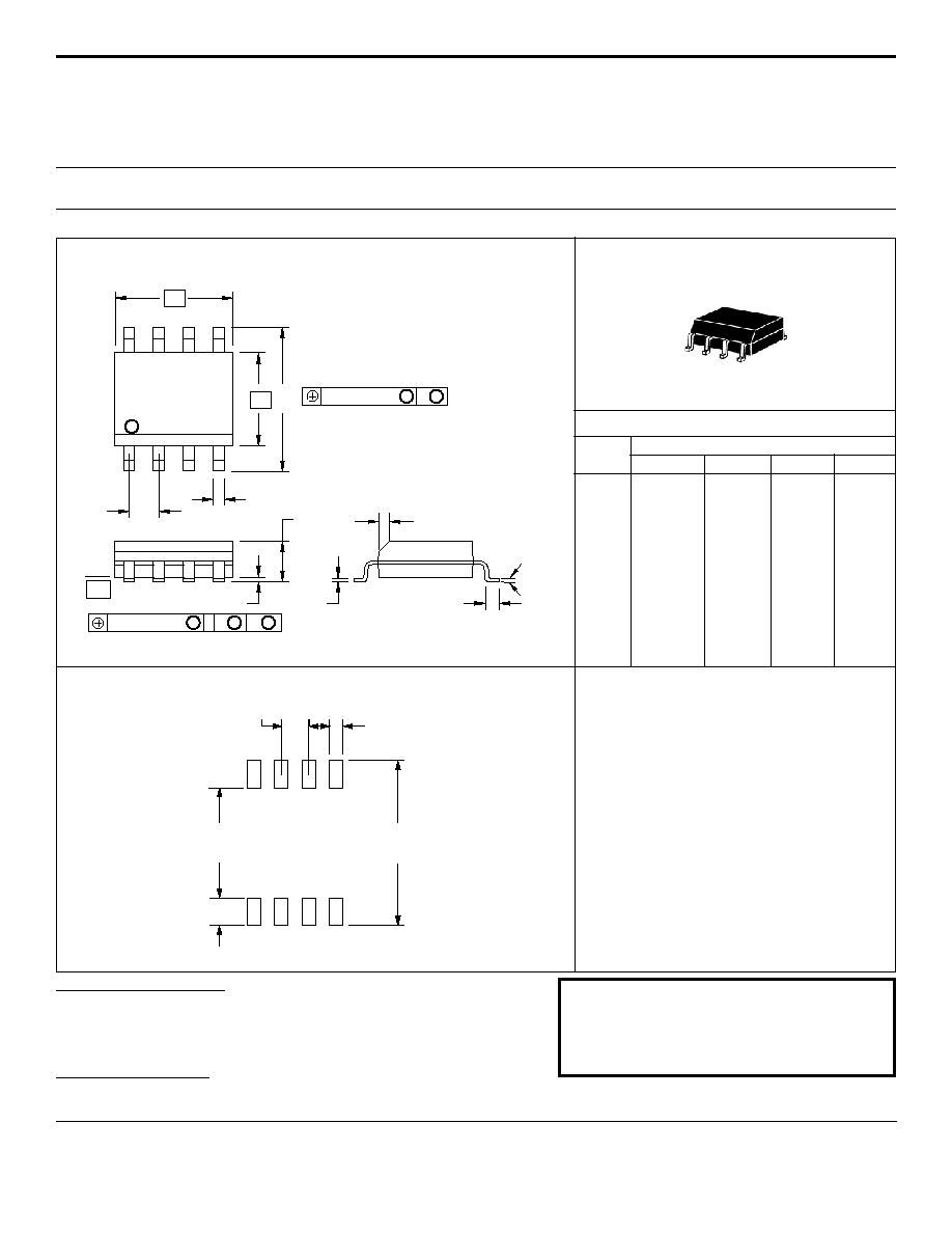
PACKAGE OUTLINE & DIMENSIONS
ProTek Devices
2929 South Fair Lane, Tempe, AZ 85282
Tel: 602-431-8101 Fax: 602-431-2288
E-Mail: sales@protekdevices.com
Web Site: www.protekdevices.com
COPYRIGHT © ProTek Devices 2001
SPECIFICATIONS: ProTek reserves the right to change the electrical and or mechanical characteristics described herein without notice (except JEDEC).
DESIGN CHANGES: ProTek reserves the right to discontinue product lines without notice, and that the final judgement concerning selection and specifications is the buyer's and that in furnishing engineering and
technical assistance, ProTek assumes no responsibility with respect to the selection or specifications of such products.
A
B
C
D
F
G
J
K
P
R
4.80
3.80
1.35
0.35
0.40
1.27 BSC
0.18
0.10
5.80
0.25
5.00
4.00
1.75
0.49
1.250
1.27 BSC
0.25
0.25
6.20
0.50
0.189
0.150
0.054
0.014
0.016
0.05 BSC
0.007
0.004
0.229
0.010
0.196
0.157
0.068
0.019
0.049
0.05 BSC
0.009
0.008
0.244
0.019
DIM
MIN
MAX
MIN
MAX
MILLIMETERS
INCHES
PACKAGE DIMENSIONS
NOTES:
1. - T - = Seating Plane and Datum Surface.
2. Dimensions "A" and "B" are Datum.
3. Dimensions "A" and "B" do not include mold
protrusion.
4. Maximum mold protrusion is 0.015" (0.380 mm)
per side.
5. Dimensioning and tolerances per ANSI Y14.5M,
1982.
6. Dimensions are exclusive of mold flash and metal
burrs.
-A-
P
-B-
D
G
8
5
4
1
-T-
K
C
R X 45
∫
J
F
0
∫
- 10
∫
0.010" (0.25 MM)
M
B
M
4 PL
0.010" (0.25 MM)
S
B
M
8 PL
T
A
S
PACKAGE OUTLINE
SO-8
0.030"
±
0.005"
0.050"
±
0.005"
0.160"
±
0.005"
0.045"
±
0.005"
0.245" MIN
MOUNTING PAD
06009 Rev 1 -11/01
TAPE & REEL PACKAGING:
Surface mount product is taped and reeled in accordance with EIA-481, reel quantites
and sizes are as follows:
7 Inch Reel - 1,000 pieces per reel; 13 Inch Reel - 2,500 pieces per reel