SMP6LC05-2P
thru
SMP6LC24-2P
1
05088.R4 3/05
www.protekdevices.com
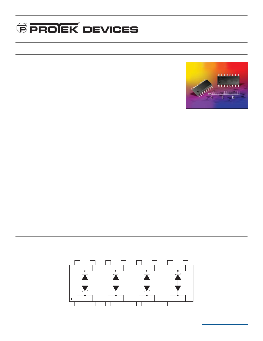
LOW CAPACITANCE TVS ARRAY
Only One Name Means ProTek'TionTM
APPLICATIONS
T1/E1
Cellular Phones
Portable Electronics
Wireless LANs
Video Inputs
IEC COMPATIBILITY (EN61000-4)
61000-4-2 (ESD): Air - 15kV, Contact - 8kV
61000-4-4 (EFT): 40A - 5/50ns
61000-4-5 (Surge): 8/20µs - 95A, L4(Line-Gnd) & 48A, L4(Line-Line) & 83A, L2(Power)
FEATURES
3,600 Watts Peak Pulse Power per Line (tp=8/20µs)
600 Watts Peak Pulse Power per Line (tp=10/1000µs)
Bidirectional Configuration
High Surge Capability: 80A (10/1000µs)
Available in Multiple Voltages
Protects Two (2) Bidirectional Lines
LOW CAPACITANCE: < 30pF per LINE PAIR
RoHS Compliant in Lead-Free Versions
MECHANICAL CHARACTERISTICS
Molded JEDEC SO-16 Package
Weight 0.15 grams (Approximate)
Available in Tin-Lead or Lead-Free Pure-Tin Plating(Annealed)
Solder Reflow Temperature:
Tin-Lead - Sn/Pb, 85/15: 240-245∞C
Pure-Tin - Sn, 100: 260-270∞C
Flammability rating UL 94V-0
16mm Tape and Reel Per EIA Standard 481
Marking: Logo, Part Number, Date Code & Pin One Defined By Dot on Top of Package
SO-16
05088
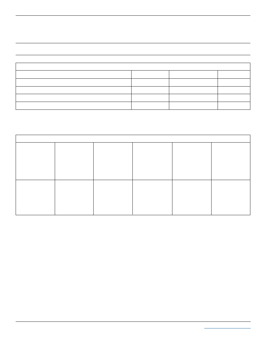
PIN CONFIGURATION
1
2
5
4
16
3
6
7
8
9
10
11
12
13
14
15
2
www.protekdevices.com
05088.R4 3/05
SMP6LC05-2P
thru
SMP6LC24-2P
DEVICE CHARACTERISTICS
MAXIMUM RATINGS @ 25∞C Unless Otherwise Specified
Peak Pulse Power (t
p
= 8/20µs)
Operating Temperature
SYMBOL
VALUE
-55
∞
C to 150
∞
C
∞C
∞C
-55
∞
C to 150
∞
C
Watts
UNITS
3,600
T
J
P
PP
T
STG
PARAMETER
Storage Temperature
Peak Pulse Power (t
p
= 10/1000µs) - See Figure 1
Watts
600
P
PP
ELECTRICAL CHARACTERISTICS PER LINE @ 25∞C Unless Otherwise Specified
PART
NUMBER
(Note 1)
RATED
STAND-OFF
VOLTAGE
V
WM
VOLTS
MINIMUM
BREAKDOWN
VOLTAGE
@ 1mA
V
(BR)
VOLTS
MAXIMUM
LEAKAGE
CURRENT
@ V
WM
I
D
µA
MAXIMUM
CLAMPING
VOLTAGE
(See Fig. 2)
@ I
PP
= 10A
V
C
VOLTS
SMP6LC05-2P
SMP6LC6.5-2P
SMP6LC08-2P
SMP6LC12-2P
SMP6LC15-2P
SMP6LC24-2P
5.0
6.5
8.0
12.0
15.0
24.0
6.0
7.2
8.5
13.3
16.7
26.7
300
300
25
2
2
2
9.6
12.4
13.6
19.9
24.4
38.9
15
15
15
15
15
15
TYPICAL
CAPACITANCE
@0V, 1MHz
C
pF
Note 1:
Do no surge from pins 15/16 to 1/2, 3/4 to 13/14, 11/12 to 5/6 and 7/8 to 9/10. PIV typically greater than 100 Volts for each rectifier diode.

3
www.protekdevices.com
05088.R4 3/05
SMP6LC05-2P
thru
SMP6LC24-2P
GRAPHS
0 1 2 3
t - Time - µs
0
50
100
I
PP
- Peak Pulse Current - % of I
PP
TEST
WAVEFORM
PARAMETERS
t
f
= 10µs
t
d
= 1,000µs
t
f
Peak Value I
PP
e
-t
FIGURE 2
PULSE WAVE FORM
t
d
= t
I
PP
/2
0 25 50 75 100 125 150
T
L
- Lead Temperature - ∞C
20
40
60
80
100
% Of Rated Power
Peak Pulse Power
10/1000µs
Average Power
FIGURE 3
POWER DERATING CURVE
0
0.1 1 10 100 1,000 10,000 100,000
t
d
- Pulse Duration - µs
600W 10/1000µs Waveform
0.1
1
10
100
P
PP
- Peak Pulse Power - kW
FIGURE 1
PEAK PULSE POWER VS PULSE TIME

4
www.protekdevices.com
05088.R4 3/05
SMP6LC05-2P
thru
SMP6LC24-2P
COPYRIGHT © ProTek Devices 2005
SPECIFICATIONS: ProTek reserves the right to change the electrical and or mechanical
characteristics described herein without notice (except JEDEC).
DESIGN CHANGES: ProTek reserves the right to discontinue product lines without notice, and that
the final judgement concerning selection and specifications is the buyer's and that in furnishing
engineering and technical assistance, ProTek assumes no responsibility with respect to the
selection or specifications of such products.
PACKAGE OUTLINE & DIMENSIONS
ProTek Devices
2929 South Fair Lane, Tempe, AZ 85282
Tel: 602-431-8101 Fax: 602-431-2288
E-Mail:
sales@protekdevices.com
Web Site:
www.protekdevices.com
A
B
C
D
F
G
J
K
P
R
10.00
4.00
1.75
0.49
1.25
1.27 BSC
0.25
0.25
6.20
0.50
0.386
0.150
0.054
0.014
0.016
0.05 BSC
0.008
0.004
0.229
0.010
0.393
0.157
0.068
0.019
0.049
0.05 BSC
0.009
0.009
0.244
0.019
9.80
3.80
1.35
0.35
0.40
1.27 BSC
0.19
0.10
5.80
0.25
DIM
MIN
MAX
MIN
MAX
MILLIMETERS
INCHES
PACKAGE DIMENSIONS
NOTES
1. - T - = Seating Plane and Datum Surface.
2. Dimensions "A" and "B" are Datum.
3. Dimensions "A" and "B" do not include mold
protrusions.
4. Maximum mold protrusion is 0.015" (0.380 mm)
per side.
5. Dimensioning and tolerances per ANSI Y14.5M,
1982.
6. Dimensions are exclusive of mold flash and metal
burrs.
PACKAGE OUTLINE
SO-16
MOUNTING PAD
M
-A-
-B- P
D
G
-T-
K
C
J
R X 45
∫
F
0.010" (0.25 MM)
M
B
M
8 PL
0.010" (0.25 MM)
S
B
M
16 PL
T
A
S
16
9
8
1
0
∫
- 7
∫
0.050" TYP
0.030"
±
0.005"
0.245" MIN
0.160"
±
0.005"
0.045"
±
0.005"
TAPE & REEL/BULK ORDERING NOMENCLATURE
1. Surface mount product is taped and reeled in accordance
with EIA-481.
2. Suffix-T7 = 7 Inch Reel - 1,000 pieces per 16mm tape,
i.e.,
SMP6LC05-2P-T7.
3. Suffix-T13 = 13 Inch Reel - 2,500 pieces per 16mm tape,
i.e.,
SMP6LC05-2P-T13.
4. Suffix - LF = Lead-Free, Pure-Tin Plating,
i.e.,
SMP6LC05-2-LF-T7.
5. No Suffix = Product Shipped in Tubes of 37 pcs per Tube.
Outline & Dimensions: Rev 1 - 11/01, 06007