s
Fully integrated 10BASE-T module for adapter, hub, and
motherboard applications.
s
Designed to meet IEEE802.3i-1993 10BASE-T specifications.
s
Low profile surface mount package
s
235∞C peak infrared reflow temperature rating
s
Operating temperature -40∞C to +85∞C.
s
Parts can be screened to MIL-T-21038 and other military specific requirements
T
T E
E C
C H
H N
N I
IT
T R
R O
O L
L
Military-Grade
10BASE-T
interface module
Part
Number
Insertion
Loss
1-10 MHz
(dB max)π
Attenuation
XMIT
(dB min)π
Return Loss
5 to 10 MHz
(dB min)
Crosstalk
(dB min)
Common Mode Rejection
(dB min)
Pri-Sec
Isolation
(Vrms min)
30
MHz
50
MHz
100
MHz
100
ohms
98
±13 ohms
-15
5-10
MHz
-35
5-10
MHz
-60
50
MHz
-55
100
MHz
200
MHz
-45
1500
-50
-18
-35
-30
-35
-10
10B-2001
CHARACTERISTICS
MECHANICAL OUTLINES
TWO PEARL BUCK COURT
q
BRISTOL, PA 19007-6812
q
TEL 215-781-6400
q
FAX 215-781-6403
q
www.pulsespecialty.com
1) Receive and transmit sides meet IEEE 802.3i-1993 specification, transmit side is enhanced for FCC/VDE class B system emissions requirement.
Specifications reflect filter sections, additional attenuation is due to pre-distortion resistors.
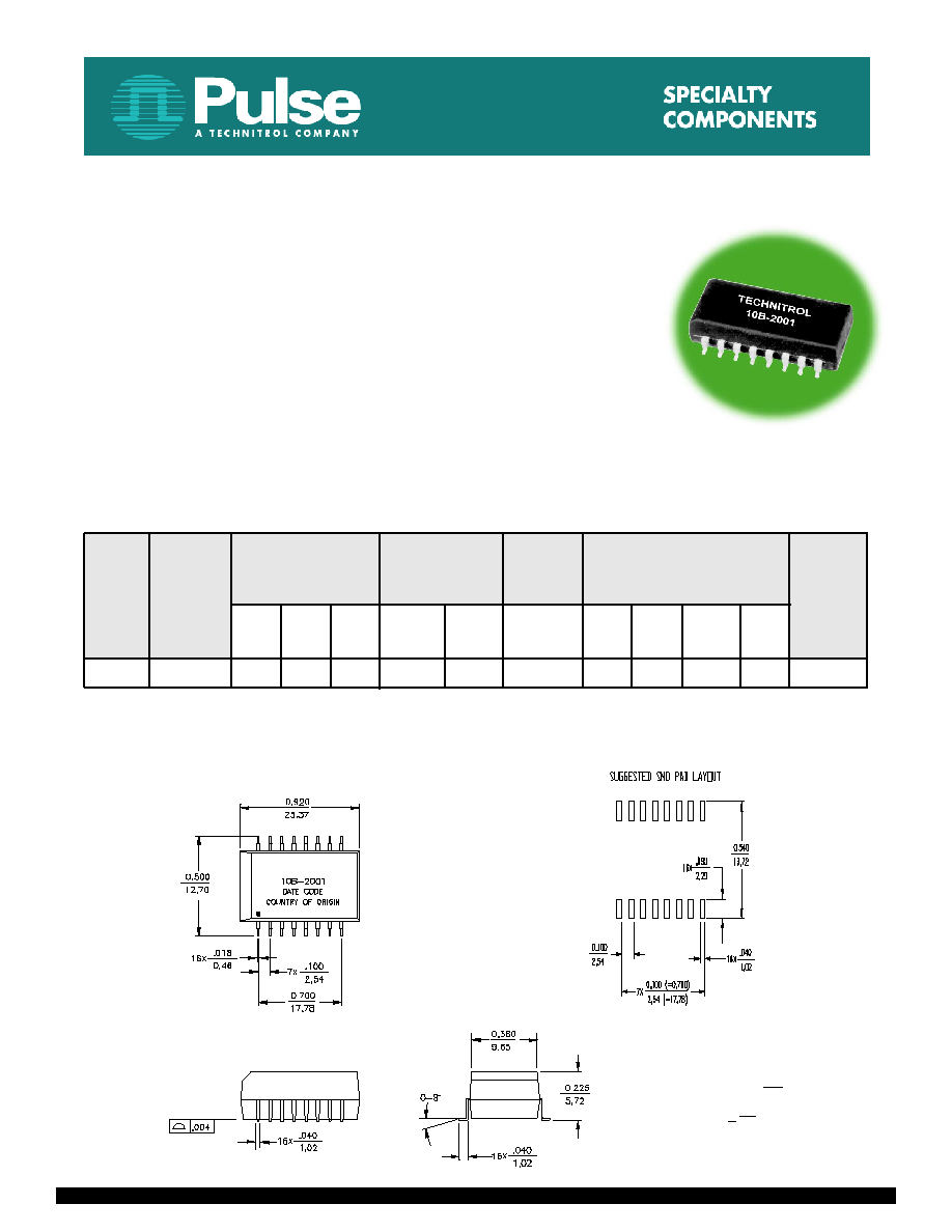
Notes:
1. Weight = 2.5 grams.
2. All dimensions are in
inches
.
mm
3. Unless otherwise specified, all
tolerances are +
0.010
.
0.254
4. All specifications and dimensions
are subject to change without notice.

APPLICATIO N NO TES
CHIP SIDE
UTP SIDE
TRANSMIT
CHANNEL
CHANNEL
RECEIVE
CHIP SIDE
UTP SIDE
The module contains low pass filters, isolation
transformers, and common mode chokes. These
components provide impedance matching,
equipment isolation, and EMI compression to
comply with IEEE requirements. User
compliance with FCC/ CSPR class B
requirements can be achieved by applying
rigorous design guidelines to suppress noise
mechanisms. Attention to high frequency signal
paths, proper PCB grounding techniques, and
component placement is critical. Pins 5 and 12,
when grounded, provide noise return paths. At
least one of these (typically pin 12) must be
coupled with bypass capacitor. Recommended
module orientation with respect to RJ45
connector is illustrated in the application circuit.
Output pins 6 through 11 should be routed with
short, matched traces to the connector for
optimum EMI performance. The robust
mechanical package withstands IR reflow
temperatures up to 235∞C. Compliant leads
provide excellent solder-joint reliability with
K.002 coplanarity. Modules are shipped in
tubes.
SCHEMATIC
TYPICAL APPLICATIO N CIRCUIT
NOT
TWO PEARL BUCK COURT
q
BRISTOL, PA 19007-6812
q
TEL 215-781-6400
q
FAX 215-781-6403
q
www.pulsespecialty.com