.045
(1.14)
.143
(3.63)
+
.029 MAX
(0.74)
.099 (2.52)
.093 (2.36)
.100
(2.54)
.500
(12.70)
.300
(7.62)
.125
(3.18)
DENOTES
ANODE
LEAD
+
.250
(6.35)
.099 (2.52)
.093 (2.36)
+
.250
(6.35)
.135 MIN
(3.43)
.029 MAX
(0.74)
.125
(3.18)
.080 DIA
(2.03)
.045
(1.14)
.200
(5.08)
.040
(1.02)
.100
(2.54)
+
DENOTES
ANODE
LEAD
+
DENOTES
ANODE
LEAD
+
.150
(3.81)
.300
(7.62)
.099 (2.52)
.093 (2.36)
.080 DIA
(2.03)
.045
(1.14)
.250
(6.35)
.029 MAX
(0.74)
.200
(5.08)
.050
(1.27)
.125 MIN
(3.18)
@
PKG.
PART NUMBER
COLOR
VF
mcd
mA
FIG.
MV5000.MP1
RED
1.7
3.0
20
1
MV5300.MP1
YLW
2.1
2.0
20
1
MV5400.MP1
GRN
2.3
3.5
20
1
MV5000.MP2
RED
1.7
3.0
20
2
MV5300.MP2
YLW
2.1
2.0
20
2
MV5400.MP2
GRN
2.3
3.5
20
2
MV5000.MP3
RED
1.7
3.0
20
3
MV5300.MP3
YLW
2.1
2.0
20
3
MV5400.MP3
GRN
2.3
3.5
20
3
INTEGRAL RESISTOR
MR5000.MP1
RED
5.0
.6
3
1
MR5010.MP1
RED
5.0
1.2
6
1
MR5020.MP1
RED
5.0
2.0
16
1
MR5310.MP1
YLW
5.0
.6
5
1
MR5410.MP1
GRN
5.0
.5
5
1
MR5000.MP2
RED
5.0
.6
3
2
MR5010.MP2
RED
5.0
1.2
6
2
MR5020.MP2
RED
5.0
2.0
16
2
MR5310.MP2
YLW
5.0
.6
5
2
MR5410.MP2
GRN
5.0
.5
5
2
MR5000.MP3
RED
5.0
.6
3
3
MR5010.MP3
RED
5.0
1.2
6
3
MR5020.MP3
RED
5.0
2.0
16
3
MR5310.MP3
YLW
5.0
.6
5
3
MR5410.MP3
GRN
5.0
.5
5
3
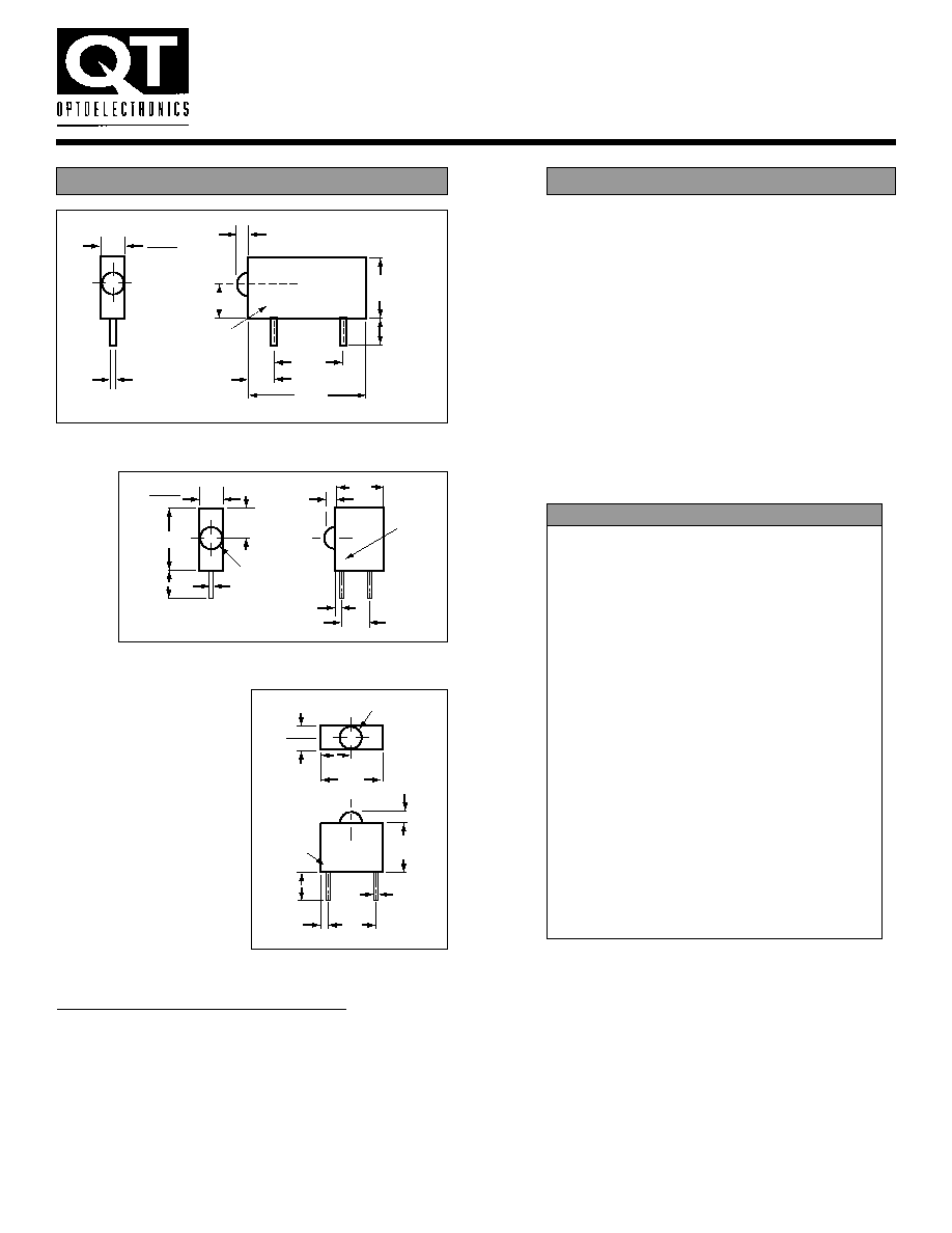
T-3/4 (Subminiature)
PACKAGE DIMENSIONS
PCB MOUNT LED INDICATORS
Page 1 of 6
DESCRIPTION
For right-angle and vertical viewing, the
QT Optoelectronics LED circuit board indicators
come in T-3/4, T-1 and T-1 3/4 lamp sizes, and in
single, dual and multiple packages. The indicators
are available in AIGaAs red, high-efficiency red,
bright red, green, yellow, and bi-color at standard
drive currents, as well as at 2 mA drive current.
To reduce component cost and save space, 5 V
and 12 V types are available with integrated
resistors. The LEDs are packaged in a black plas-
tic housing for optical contrast, and the housing
meets UL94V-0 flammability specifications.
FIG. - 1
FIG. - 2
FIG. - 3
GENERAL NOTES:
1. All dimensions are in inches (mm).
2. Tolerance is ± .015 (± .38) unless otherwise specified.
3. All electrical values are typical.
4. All parts have colored
diffused lens except those with
an asterik (*), which denotes colored
clear lens.

PCB MOUNT LED INDICATORS
Page 2 of 6
PACKAGE DIMENSIONS
@
PKG.
PART NUMBER
COLOR
VF
mcd
mA
FIG.
MV5064.MP4A
RED
1.6
1.5
20
4A
MV5364.MP4A
YELLOW
2.1
2.0
10
4A
MV5464.MP4A
GREEN
2.2
5.0
20
4A
MV5764.MP4A
H-E RED
2.0
2.0
10
4A
MV5064.MP4B
RED
1.6
1.5
20
4B
MV5364.MP4B
YELLOW
2.1
2.0
10
4B
MV5464.MP4B
GREEN
2.2
5.0
20
4B
MV5764.MP4B
H-E RED
2.0
2.0
10
4B
LOW CURRENT (2mA)
HLMP-1700.MP4A
H-E RED
1.8
2.0
2
4A
HLMP-1719.MP4A
YELLOW
1.9
2.0
2
4A
HLMP-1790.MP4A
GREEN
1.9
2.0
2
4A
HLMP-1700.MP4B
H-E RED
1.8
2.0
2
4B
HLMP-1719.MP4B
YELLOW
1.9
2.0
2
4B
HLMP-1790.MP4B
GREEN
1.9
2.0
2
4B
AIGaAs RED
HLMP-K101.MP4A
AIGaAs RED
1.8
45.0
20
4A
HLMP-K105.MP4A
AIGaAs RED*
1.8
65.0
20
4A
HLMP-K150.MP4A
AIGaAs RED
1.6
2.0
1
4A
HLMP-K155.MP4A
AIGaAs RED*
1.6
3.0
1
4A
HLMP-K101.MP4B
AIGaAs RED
1.8
45.0
20
4B
HLMP-K105.MP4B
AIGaAs RED*
1.8
65.0
20
4B
HLMP-K150.MP4B
AIGaAs RED
1.6
2.0
1
4B
HLMP-K155.MP4B
AIGaAs RED*
1.6
3.0
1
4B
INTEGRAL RESISTOR
MR5060.MP4A
RED
5.0
1.5
13
4A
MR5360.MP4A
YELLOW
5.0
4.0
10
4A
MR5460.MP4A
GREEN
5.0
4.0
12
4A
MR5760.MP4A
H-E RED
5.0
4.0
10
4A
MR5060.MP4B
RED
5.0
1.5
13
4B
MR5360.MP4B
YELLOW
5.0
4.0
10
4B
MR5460.MP4B
GREEN
5.0
4.0
12
4B
MR5760.MP4B
H-E RED
5.0
4.0
10
4B
T-1 (3mm)
@
PKG.
PART NUMBER
COLOR
VF
mcd
mA
FIG.
QLA694B-2H
B. RED/B. RED
2.1
1.4
10
4C
QLA694B-2I
H-E RED/H-E RED 2.0
6.0
10
4C
QLA694B-2G
GRN/GRN
2.1
6.0
10
4C
QLA694B-2Y
YEL/YEL
2.0
6.0
10
4C
QLA694B-HG
B. RED/GRN
2.1
1.4
10
4C
QLA694B-GY
GRN/YEL
2.1
6.0
10
4C
T-1 (3mm) bilevel
+
MAX
.180
(4.57)
.200
(5.08)
.400 MIN
(10.16)
.100 TYP
(2.54)
.025 (.63)
.015 (.37)
.120 DIA
(3.05)
.125
(3.18)
.250
(6.35)
.290 MAX
(7.37)
.185 REF
(4.70)
.025 (.63)
.015 (.37)
CATHODE
+
MAX
.180
(4.57)
.200
(5.08)
.400 MIN
(10.16)
.100 TYP
(2.54)
.025 (.63)
.015 (.37)
.120 DIA
(3.05)
.080
(2.03)
.250
(6.35)
.290 MAX
(7.37)
.185 REF
(4.70)
CATHODE
.025 (.63)
.015 (.37)
.100
(2.54)
.100
(2.54)
.169
(4.30)
+
+
.200
(5.08)
.100
(2.54)
.200
(5.08)
.380
(9.65)
.138
(3.5) MIN
.354
(9.0)
(ANODE)
.100
(2.54)
FIG. - 4A
FIG. - 4C
FIG. - 4B
GENERAL NOTES:
1. All dimensions are in inches (mm).
2. Tolerance is ± .015 (± .38) unless otherwise specified.
3. All electrical values are typical.
4. All parts have colored
diffused lens except those with
an asterik (*), which denotes colored
clear lens.
5. Custom color combinations are available.
First color indicated is on top, and the second color is on the bottom.
For example: QLA694B-GY has GRN(top)/YEL(bottom).

PCB MOUNT LED INDICATORS
Page 3 of 6
@
DIM A
PKG.
PART NUMBER
COLOR
VF
mcd
mA
in. (mm) FIG.
MV60538.MP5
RED
1.7
2.0
20
.125
(3.18)
5
MV63538.MP5
YLW
2.1
18.0
20
.125
(3.18)
5
MV64538.MP5
GRN
2.2
26.0
20
.125
(3.18)
5
MV67538.MP5
H-E RED
2.1
14.0
20
.125
(3.18)
5
MV60539.MP5
RED
1.7
3.2
20
.180
(4.57)
5
MV63539.MP5
YLW
2.1
20.0
20
.180
(4.57)
5
MV64539.MP5
GRN
2.2
28.0
20
.180
(4.57)
5
MV67539.MP5
H-E RED
2.1
15.0
20
.180
(4.57)
5
LOW CURRENT (2mA)
HLMP-47009.MP5
H-E RED
1.8
2.0
2
.180
(4.57)
5
HLMP-47199.MP5
YLW
1.9
2.0
2
.180
(4.57)
5
HLMP-47409.MP5
GRN
1.9
3.0
2
.180
(4.57)
5
AIGaAs RED
HLMP-D1019.MP5
AIGaAs RED
1.8
70.0
20
.180
(4.57)
5
HLMP-D1509.MP5
AIGaAs RED
1.6
3.0
1
.180
(4.57)
5
ULTRA BRIGHT
MV33509.MP5
YLW*
2.2
150.0
20
.180
(4.57)
5
MV34509.MP5
GRN*
2.2
150.0
20
.180
(4.57)
5
MV37509.MP5
H-E RED*
2.2
150.0
20
.180
(4.57)
5
INTEGRAL RESISTOR
MR30509.MP5
RED
5.0
2.0
13
.180
(4.57)
5
MR30519.MP5
RED
12.0
2.0
13
.180
(4.57)
5
MR33509.MP5
YLW
5.0
4.0
10
.180
(4.57)
5
MR33519.MP5
YLW
12.0
4.0
13
.180
(4.57)
5
MR34509.MP5
GRN
5.0
4.0
12
.180
(4.57)
5
MR34519.MP5
GRN
12.0
4.0
13
.180
(4.57)
5
MR37509.MP5
H-E RED
5.0
4.0
10
.180
(4.57)
5
MR37519.MP5
H-E RED
12.0
4.0
13
.180
(4.57)
5
BICOLOR**
MV54919.MP5
RED/GRN
2.3
6.0
20
.180
(4.57)
5
T-1 3/4 (5mm)
MAX
.245
(6.22)
CATHODE**
MAX
.245
(6.22)
.190 DIA
(4.83)
.242 (6.15)
.222 (5.64)
DIM A
.020
(.51)
.145 MIN
(3.68)
.100
(2.54)
.100
(2.54)
PACKAGE DIMENSIONS
FIG. - 5
+
+
+
.561 (14.25)
.537 (13.64)
.100
(2.54)
.100
(2.54)
.016
(.4)
.260
(6.6)
.100
(2.54)
.100
(2.54)
.200
(5.08)
.135
(3.5) MIN
(ANNODE)
.200
(5.08)
.022 (.8)
.006 (.4)
.183 (4.65)
.167 (4.25)
.612 (15.55)
.588 (14.95)
@
PKG.
PART NUMBER
COLOR
VF
mcd
mA
FIG.
QLA764B-3H
B. RED
2.1
1.4
10
4D
QLA764B-3I
H-E RED
2.0
6.0
10
4D
QLA764B-3G
GRN
2.1
6.0
10
4D
QLA764B-3Y
YEL
2.0
6.0
10
4D
QLA764B-HGY
B. RED/GRN/YEL
2.1
1.4
10
4D
QLA764B-YGH
YEL/GRN/B. RED
2.1
1.4
10
4D
T-1 (3mm) trilevel
FIG. - 4D
GENERAL NOTES:
1. All dimensions are in inches (mm).
2. Tolerance is ± .015 (± .38) unless otherwise specified.
3. All electrical values are typical.
4. All parts have colored
diffused lens except those with
an asterik (*), which denotes colored
clear lens.
5. A double asterik (**) denotes that the cathode, as indicated,
is the red cathode for the RED/GRN bicolor LED.
6. Custom color combinations are available.
First color indicated is on top, the second is in the middle, and the third is on the bottom.
For example: QLA764B-YGH has YEL(top)/GRN(middle)/B. RED(bottom).

PCB MOUNT LED INDICATORS
Page 4 of 6
@
DIM A
PKG.
PART NUMBER
COLOR
VF
mcd
mA
in. (mm) FIG.
MV60538.MP6
RED
1.7
2.0
20
.125 (3.18)
6
MV63538.MP6
YLW
2.1
18.0
20
.125 (3.18)
6
MV64538.MP6
GRN
2.2
26.0
20
.125 (3.18)
6
MV67538.MP6
H-E RED
2.1
14.0
20
.125 (3.18)
6
MV60539.MP6
RED
1.7
3.2
20
.180 (4.57)
6
MV63539.MP6
YLW
2.1
20.0
20
.180 (4.57)
6
MV64539.MP6
GRN
2.2
28.0
20
.180 (4.57)
6
MV67539.MP6
H-E RED
2.1
15.0
20
.180 (4.57)
6
LOW CURRENT (2mA)
HLMP-47009.MP6
H-E RED
1.8
2.0
2
.180 (4.57)
6
HLMP-47199.MP6
YLW
1.9
2.0
2
.180 (4.57)
6
HLMP-47409.MP6
GRN
1.9
3.0
2
.180 (4.57)
6
AIGaAs RED
HLMP-D1019.MP6
AIGaAS RED
1.8
70.0
20
.180 (4.57)
6
HLMP-D1509.MP6
AIGaAS RED
1.6
3.0
1
.180 (4.57)
6
ULTRA BRIGHT
MV33509.MP6
YLW*
2.2
150.0
20
.180 (4.57)
6
MV34509.MP6
GRN*
2.2
150.0
20
.180 (4.57)
6
MV37509.MP6
H-E RED*
2.2
150.0
20
.180 (4.57)
6
INTEGRAL RESISTOR
MR30509.MP6
RED
5.0
2.0
13
.180 (4.57)
6
MR30519.MP6
RED
12.0
2.0
13
.180 (4.57)
6
MR33509.MP6
YLW
5.0
4.0
10
.180 (4.57)
6
MR33519.MP6
YLW
12.0
4.0
13
.180 (4.57)
6
MR34509.MP6
GRN
5.0
4.0
12
.180 (4.57)
6
MR34519.MP6
GRN
12.0
4.0
13
.180 (4.57)
6
MR37509.MP6
H-E RED
5.0
4.0
10
.180 (4.57)
6
MR37519.MP6
H-E RED
12.0
4.0
13
.180 (4.57)
6
BICOLOR**
MV54919.MP6
RED/GRN
2.3
6.0
20
.180 (4.57)
6
T-1 3/4 (5mm)
@
DIM A
PKG.
PART NUMBER
COLOR
VF
mcd
mA
in.
(mm) FIG.
MV60538.MP7
RED
1.7
2.0
20
.125
(3.18)
7
MV63538.MP7
YLW
2.1
18.0
20
.125
(3.18)
7
MV64538.MP7
GRN
2.2
26.0
20
.125
(3.18)
7
MV67538.MP7
H-E RED
2.1
14.0
20
.125
(3.18)
7
MV60539.MP7
RED
1.7
3.2
20
.183
(4.65)
7
MV63539.MP7
YLW
2.1
20.0
20
.183
(4.65)
7
MV64539.MP7
GRN
2.2
28.0
20
.183
(4.65)
7
MV67539.MP7
H-E RED
2.1
15.0
20
.183
(4.65)
7
LOW CURRENT (2mA)
HLMP-47009.MP7
H-E RED
1.8
2.0
2
.183
(4.65)
7
HLMP-47199.MP7
YLW
1.9
2.0
2
.183
(4.65)
7
HLMP-47409.MP7
GRN
1.9
3.0
2
.183
(4.65)
7
AIGaAs RED
HLMP-D1019.MP7
AIGaAs RED
1.8
70.0
20
.183
(4.65)
7
HLMP-D1509.MP7
AIGaAs RED
1.6
3.0
1
.183
(4.65)
7
ULTRA BRIGHT
MV33509.MP7
YLW*
2.2
150.0
20
.183
(4.65)
7
MV34509.MP7
GRN*
2.2
150.0
20
.183
(4.65)
7
MV37509.MP7
H-E RED*
2.2
150.0
20
.183
(4.65)
7
INTEGRAL RESISTOR
MR30509.MP7
RED
5.0
2.0
13
.183
(4.65)
7
MR30519.MP7
RED
12.0
2.0
13
.183
(4.65)
7
MR33509.MP7
YLW
5.0
4.0
10
.183
(4.65)
7
MR33519.MP7
YLW
12.0
4.0
13
.183
(4.65)
7
MR34509.MP7
GRN
5.0
4.0
12
.183
(4.65)
7
MR34519.MP7
GRN
12.0
4.0
13
.183
(4.65)
7
MR37509.MP7
H-E RED
5.0
4.0
10
.183
(4.65)
7
MR37519.MP7
H-E RED
12.0
4.0
13
.183
(4.65)
7
BICOLOR**
MV54919.MP7
RED/GRN
2.3
6.0
20
.183
(4.65)
7
T-1 3/4 (5mm)
MAX
.245
(6.22)
CATHODE**
MAX
.245
(6.22)
.145 (3.68) MIN
.020
(.51)
.100
(2.54)
DIM A
.190 DIA
(4.83)
.242 (6.15)
.222 (5.64)
PACKAGE DIMENSIONS
.200
(5.08)
DIM A
MAX
.245
(6.22)
CATHODE**
MAX
.245
(6.22)
.145 MIN
(3.68)
.190 DIA
(4.83)
.100
(2.54)
.020
(.51)
.020
(.51)
.355 (9.02)
FIG. - 6
FIG. - 7
GENERAL NOTES:
1. All dimensions are in inches (mm).
2. Tolerance is ± .015 (± .38) unless otherwise specified.
3. All electrical values are typical.
4. All parts have colored
diffused lens except those with
an asterik (*), which denotes colored
clear lens.
5. A double asterik (**) denotes that the cathode, as indicated,
is the red cathode for the RED/GRN bicolor LED.
6. Custom color combinations are available.

PCB MOUNT LED INDICATORS
Page 5 of 6
@
DIM A
PKG.
PART NUMBER
COLOR
VF
mcd
mA
in.
(mm) FIG.
MV60538.MP8
RED
1.7
2.0
20
.140
(3.56)
8
MV63538.MP8
YLW
2.1
18.0
20
.140
(3.56)
8
MV64538.MP8
GRN
2.2
26.0
20
.140
(3.56)
8
MV67538.MP8
H-E RED
2.1
14.0
20
.140
(3.56)
8
MV60539.MP8
RED
1.7
3.2
20
.195
(4.95)
8
MV63539.MP8
YLW
2.1
20.0
20
.195
(4.95)
8
MV64539.MP8
GRN
2.2
28.0
20
.195
(4.95)
8
MV67539.MP8
H-E RED
2.1
15.0
20
.195
(4.95)
8
LOW CURRENT (2mA)
HLMP-47009.MP8
H-E RED
1.8
2.0
2
.195
(4.95)
8
HLMP-47199.MP8
YLW
1.9
2.0
2
.195
(4.95)
8
HLMP-47409.MP8
GRN
1.9
3.0
2
.195
(4.95)
8
ULTRA BRIGHT
MV33509.MP8
YLW*
2.2
150.0
20
.195
(4.95)
8
MV34509.MP8
GRN*
2.2
150.0
20
.195
(4.95)
8
MV37509.MP8
H-E RED*
2.2
150.0
20
.195
(4.95)
8
INTEGRAL RESISTOR
MR30509.MP8
RED
5.0
2.0
13
.195
(4.95)
8
MR30519.MP8
RED
12.0
2.0
13
.195
(4.95)
8
MR33509.MP8
YLW
5.0
4.0
10
.195
(4.95)
8
MR33519.MP8
YLW
12.0
4.0
13
.195
(4.95)
8
MR34509.MP8
GRN
5.0
4.0
12
.195
(4.95)
8
MR34519.MP8
GRN
12.0
4.0
13
.195
(4.95)
8
MR37509.MP8
H-E RED
5.0
4.0
10
.195
(4.95)
8
MR37519.MP8
H-E RED
12.0
4.0
13
.195
(4.95)
8
BICOLOR**
MV54919.MP8
RED/GRN
2.3
6.0
20
.195
(4.95)
8
T-1 3/4 (5mm) multiple
PACKAGE DIMENSIONS
CATHODE**
.250 TYP
(6.35)
.190
(4.83)
.020 TYP
(.51)
.100
(2.54)
.015
TYP
.100 TYP
(2.54)
.250
(6.35)
.145 MIN
(3.68)
.250 TYP
(6.35)
1.01
(25.65)
DIM A
@
DIM A
PKG.
PART NUMBER
COLOR
VF
mcd
mA
in.
(mm) FIG.
MV60538.MP8A
RED
1.7
2.0
20
.140
(3.56)
8A
MV63538.MP8A
YLW
2.1
18.0
20
.140
(3.56)
8A
MV64538.MP8A
GRN
2.2
26.0
20
.140
(3.56)
8A
MV67538.MP8A
H-E RED
2.1
14.0
20
.140
(3.56)
8A
MV60539.MP8A
RED
1.7
3.2
20
.195
(4.95)
8A
MV63539.MP8A
YLW
2.1
20.0
20
.195
(4.95)
8A
MV64539.MP8A
GRN
2.2
28.0
20
.195
(4.95)
8A
MV67539.MP8A
H-E RED
2.1
15.0
20
.195
(4.95)
8A
LOW CURRENT (2mA)
HLMP-47009.MP8A
H-E RED
1.8
2.0
2
.195
(4.95)
8A
HLMP-47199.MP8A
YLW
1.9
2.0
2
.195
(4.95)
8A
HLMP-47409.MP8A
GRN
1.9
3.0
2
.195
(4.95)
8A
ULTRA BRIGHT
MV33509.MP8A
YLW*
2.2
150.0
20
.195
(4.95)
8A
MV34509.MP8A
GRN*
2.2
150.0
20
.195
(4.95)
8A
MV37509.MP8A
H-E. RED*
2.2
150.0
20
.195
(4.95)
8A
INTEGRAL RESISTOR
MR30509.MP8A
RED
5.0
2.0
13
.195
(4.95)
8A
MR30519.MP8A
RED
12.0
2.0
13
.195
(4.95)
8A
MR33509.MP8A
YLW
5.0
4.0
10
.195
(4.95)
8A
MR33519.MP8A
YLW
12.0
4.0
13
.195
(4.95)
8A
MR34509.MP8A
GRN
5.0
4.0
12
.195
(4.95)
8A
MR34519.MP8A
GRN
12.0
4.0
13
.195
(4.95)
8A
MR37509.MP8A
H-E RED
5.0
4.0
10
.195
(4.95)
8A
MR37519.MP8A
H-E RED
12.0
4.0
13
.195
(4.95)
8A
BICOLOR**
MV54919.MP8A
RED/GRN
2.3
6.0
20
.195
(4.95)
8A
T-1 3/4 (5mm) multiple
.250
(6.35)
DIM A
.190
(4.83)
.195
(4.95)
1.01 (25.65)
.250 TYP
(6.35)
.020 TYP
(.51)
.250 TYP
(6.35)
.100 TYP
(2.54)
.145 MIN
(3.68)
.250
(6.35)
CATHODE**
SPECIFIC NOTES:
For T-1 3/4 (5mm) multiple, multiples of four is the standard configuration.
Options -- To obtain units in multiples of two add a "-2" suffix to the
part number (i.e. MV64539.MP8-2). To obtain units in multiples of
three add a "-3" suffix.
FIG. - 8
FIG. - 8A
GENERAL NOTES:
1. All dimensions are in inches (mm).
2. Tolerance is ± .015 (± .38) unless otherwise specified.
3. All electrical values are typical.
4. All parts have colored
diffused lens except those with
an asterik (*), which denotes colored
clear lens.
5. A double asterik (**) denotes that the cathode, as indicated,
is the red cathode for the RED/GRN bicolor LED.
6. Custom color combinations are available.