 | –≠–ª–µ–∫—Ç—Ä–æ–Ω–Ω—ã–π –∫–æ–º–ø–æ–Ω–µ–Ω—Ç: SY01-S3 | –°–∫–∞—á–∞—Ç—å:  PDF PDF  ZIP ZIP |
SYNCHRONOUS EQUIPMENT
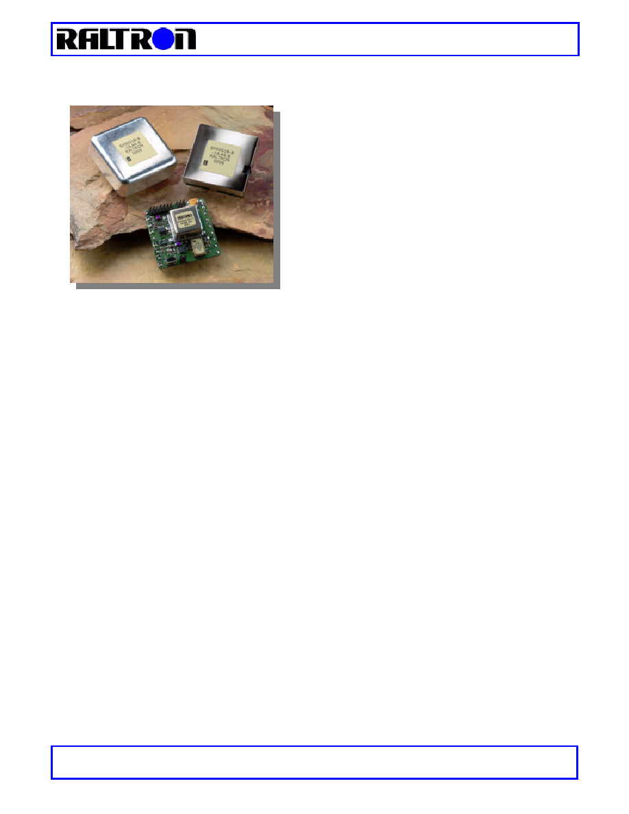
OCXO BASED STRATUM 3 CLOCK UNIT ≠ SY01-S3
RALTRON ELECTRONICS CORP.
ßß
10651 N.W.19
th
St
ßß
Florida 33172
ßß
U.S.A.
Tel: 305 593-6033
ßß
Fax: 305-594-3973
ßß
e-mail: sales@raltron.com
ßß
Internet: http:/www.raltron.com
SY01-S3
Date: May 20 , 2002
∑
INTRODUCTION
The SY01-S3 is an accurate time and frequency source that has
been designed as a module level subsystem.
The module is designed to work within ATM, SONET, SDH, and
wireless systems where synchronization is vital.
The SY01-S3 is an OCXO based excellent synchronization
solution for timing designed for Stratum 3 applications.
∑
FEATURES
A Hardware/Software synchronization solution for timing, jitter and wander concerns in a single module.
Complies with ITU-T Recommendations G.813 and ETSI-ETS 300 462-4 and Bellcore GR-1244-CORE for Stratum
3 applications.
Supports four modes of operation: Locked to Reference 1, Locked to Reference 2, Holdover and Free-run.
Accepts reference inputs from two independent sources from
8 kHz to 77.76 MHz
.
Provides two outputs
up to 77.76 MHz
.
Loop filtering utilizing application specific software in the digital signal processor (DSP).
Continuously monitors and evaluate input reference signals.
Creates a history buffer for Holdover mode operation.
Alarm and status signal.
Host interface and JTAG port.
Small dimensions of 1.80X1.80X 0.65 inch (open pkg)
∑
APPLICATION
The SY01-S3 performs clock regeneration as a Synchronous Equipment Clock (SEC), or STRATUM 3 in ATM, SDH,
PDH, and SONET networks. It is designed for manufacturers of network equipment, especially Access Switches, Core
Switches, Cross Connects, Digital Multiplexers-Exchangers, and SDH/SONET equipment. The unit is also suitable for
PCS, WLL, and Wireless Base Stations. Wherever a Timing unit with high performance specifications is required, the
SY01-S3 can be integrated into the network system and provide all necessary frequencies and interfaces. The input
stage can receive two different input reference signals at various rates from 4 kHz to 77.76 MHz. An optional
application can be achieved by integrating the SY01-S3 with a low cost GPS receiver and locking it to the GPS 1 pps
output signal.
SYNCHRONOUS EQUIPMENT
OCXO BASED STRATUM 3 CLOCK UNIT ≠ SY01-S3
RALTRON ELECTRONICS CORP.
ßß
10651 N.W.19
th
St
ßß
Florida 33172
ßß
U.S.A.
Tel: 305 593-6033
ßß
Fax: 305-594-3973
ßß
e-mail: sales@raltron.com
ßß
Internet: http:/www.raltron.com
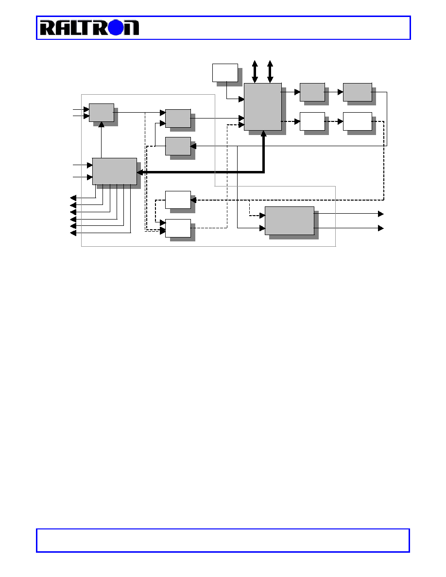
Figure 1. - The functional block diagram of SY01-S3
∑
DESCRIPTION
The SY01-S3 synchronization module is a Digital PLL (DPLL), which utilizes application specific software in the digital
signal processor (DSP). The DSP is complemented by fast hardware logic (CPLD) where all multiplexers, counters,
dividers, phase detectors, output frequency converters and other control logic circuits are completely implemented.
The functional block diagram with maximum configuration is shown in figure 1. Depending on the application, the user
can specify an appropriate configuration to fit their system requirements. The basic configuration utilizes one DPLL
with an OCXO as on-board oscillator, shown in figure 1 as the shaded boxes. The OCXO is driven by a digital-to-
analog converter (DAC1) and provides the accurate and stable signal under all conditions. The output frequency
converters scale the output frequency from the oscillator. For other configurations, please contact Raltron.
¸
¸
The module operates in the following four timing modes:
Free-run
In this mode the unit is unlocked to either of the inputs. The accuracy of the output frequencies in this mode is
±4.6ppm. Free-run mode is typically used when a master clock source is required, not valid history of data for the
Holdover mode, or immediately following system power-up before network synchronization is achieved. In the Free-run
Mode, the SY01-S3 provides timing and synchronization signals that are based on the accuracy of on-board
oscillators only, and are not synchronized to the reference signals.
Holdover
In this mode the module has lost its reference inputs and is utilizing stored timing data, called history, to control the
output frequency. Holdover Mode is typically used while network synchronization is temporarily disrupted. In Holdover
Mode, the SY01-S3 provides timing, based on data from the history buffer, while unlocked to an external reference
signal. The history data is determined while the device is locked to an external reference signal. The stability of the
output signal in holdover mode depends primarily on the stability of on-board oscillator and environment effects where
the clock is mounted. The SY01-S3 uses an OCXO as an on-board oscillator but other types of oscillators are
available.
˜
˜
N
PD1
PD2
MUX
CONTROL
LOGIC
˜
˜
M
DSP
FLASH
RAM
DAC
1
DAC
2
OCXO
VCXO
Temp.
Sensor
OUTPUT
FREQUENCY
CONVERTERS
EX REF1
EX REF2
CNT1
CNT2
ALARM OUT
PLL UNLOCK
HOLDOVER
REF 1
REF 2
FREE RUN
SCI
J-TAG
OUT
OPT OUT
CPLD
SYNCHRONOUS EQUIPMENT
OCXO BASED STRATUM 3 CLOCK UNIT ≠ SY01-S3
RALTRON ELECTRONICS CORP.
ßß
10651 N.W.19
th
St
ßß
Florida 33172
ßß
U.S.A.
Tel: 305 593-6033
ßß
Fax: 305-594-3973
ßß
e-mail: sales@raltron.com
ßß
Internet: http:/www.raltron.com
Locked to Ref.1
In this mode the output of the module is phase locked to input reference 1.
Locked to Ref.2
In this mode the output of the module is phase locked to input reference 2.
The REF1 or REF2 Modes are typically used when a slave clock source is synchronized to the network. In these
modes, the SY01-S3 provides timing signals, which are synchronized, to one of two references inputs (REF1 or
REF2). The input reference signals may have a variety of nominal frequencies, which is typically specified by the end
user. When the modes are selected the unit goes through a reference evaluation, and then a frequency acquisition,
and finally to phase locking.
∑
Input References
The SY01-S3 module accepts two input references EX REF1 and EX REF2. End users can specify the frequencies
within a range of 8 kHz to 77.76 MHz. The input reference signals are HCMOS/TTL levels with timing characteristic in
according to Bellcore GR-1244-core 3.2.1.R3-1 or equivalent standards. Please note that the end user must specify
the two input frequencies at the time of order.
∑
Output Signals
The SY01-S3 module provides two output signals OUT and OPT OUT. The outputs are generated by the internal
oscillator and scaled by the output frequency converters. The performance of the module significantly depends on the
internal oscillator and special care was taken to define its specification. A Oven Controlled Crystal Oscillator (OCXO)
is used as the internal oscillator. The frequency of the oscillator is specified according to the network application
where the SY01-S3 will be used. The frequency converters divide signal from the oscillator to the specified
frequencies.
∑
The SY01 Operation mode
By changing the control inputs the user can change the state of the SY01 according to the state diagram. The
SY01 offers two ways to manage state machine:
J1 jumper
State diagram control
Open
Manual
Closed
Automatic
The behavior of the Manual and Automatic controls are shown on the figures 2 and 3 with an explanation for each
transition. In the Automatic control the SY01 can be automatically switched to the reference (if available)
regardless of status of the control inputs. In Manual control the unit waits for control inputs to be changed. In both
modes the unit will go to the REFERENCE EVALUATION if the previously lost reference is required.
∑
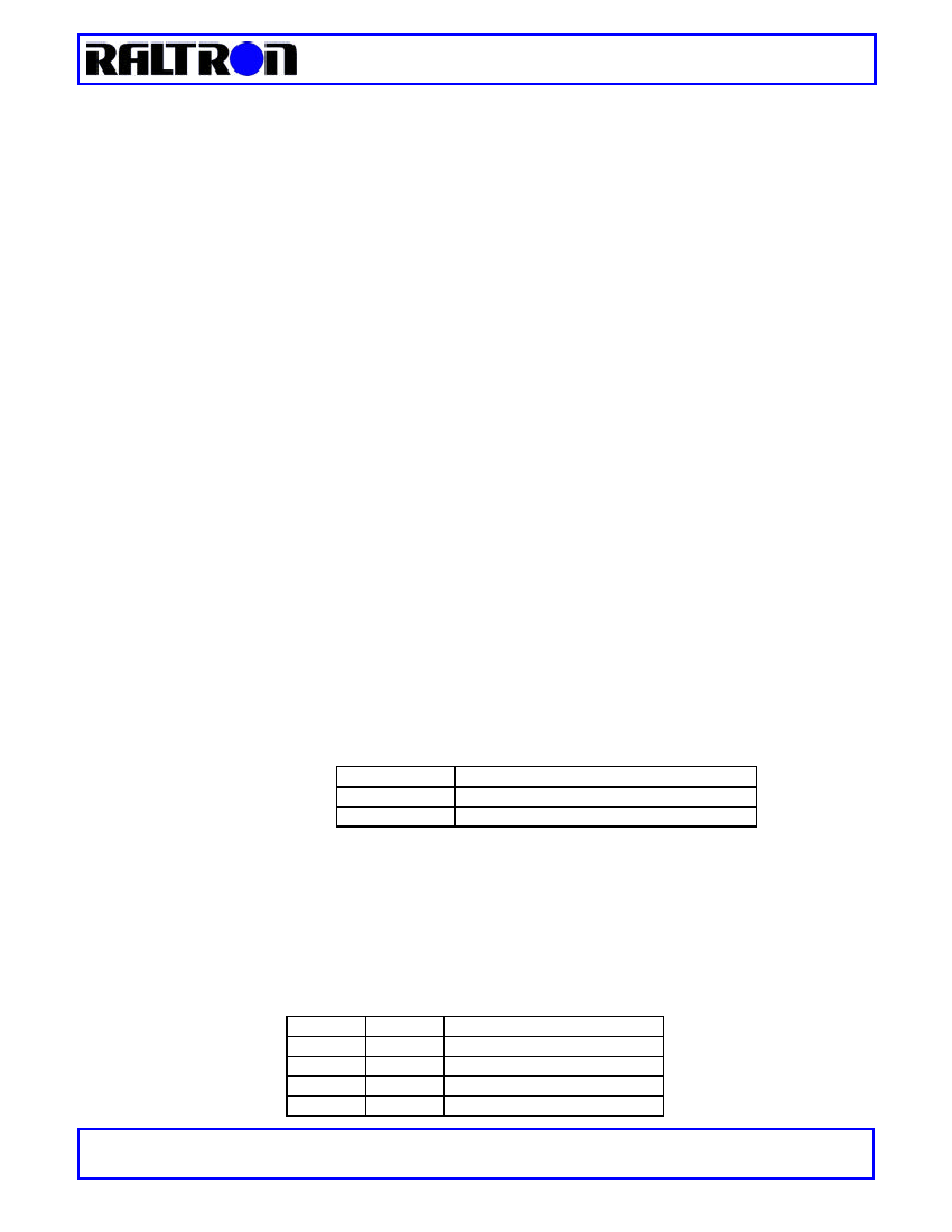
Control
Two controls are available for the user to control the operation of the SY01. The two external inputs CNT1 and CNT2
provide this feature. Below, the truth table shows behavior of the SY01 module according to the control inputs states.
CNT2
CNT1
MODE OF OPERATION
0
0
Free-run
0
1
Locked to REF1
1
0
Locked to REF2
1
1
Holdover
SYNCHRONOUS EQUIPMENT
OCXO BASED STRATUM 3 CLOCK UNIT ≠ SY01-S3
RALTRON ELECTRONICS CORP.
ßß
10651 N.W.19
th
St
ßß
Florida 33172
ßß
U.S.A.
Tel: 305 593-6033
ßß
Fax: 305-594-3973
ßß
e-mail: sales@raltron.com
ßß
Internet: http:/www.raltron.com
∑
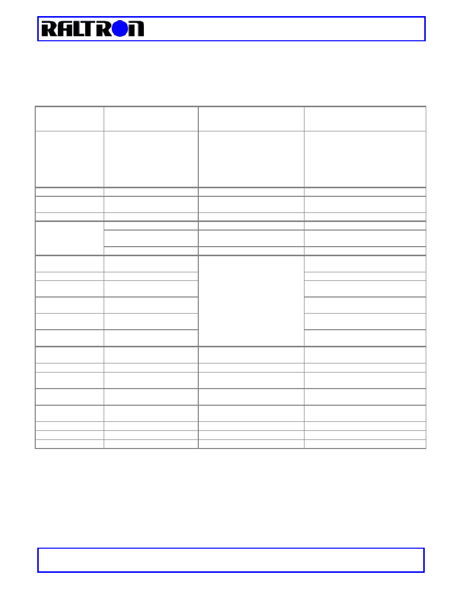
SPECIFICATIONS
General
Specifications
Mechanical
2" (D) x 2" (W) x 0.75" (H)
1.85" (D) x 1.85" (W) x 0.7" (H)
1.8" (D) x 1.8" (W) x 0.65" (H)
Hermetically Sealed Metal box
Metal Box
Module on PCB
Power Supply
5VDC
Regulated
Warm Up Current Supply
900mA max
Steady State Current Supply
400mA max.
Operating Temperature
-20∞C to 70∞C
Other ranges available on request
Storage Temperature
-40∞ to 85∞C
Humidity
5% to 95% non-condensing
Internal Oscillators
OCXO
Input Signals
Number of Inputs
2
Input reference frequency
8kHz to 77.76MHz
User selectable
Signal Level
HCMOS/TTL Compatible
Time Reference characteristics
Bellcore: GR-1244-core 3.2.1.R3-1
Number of Outputs
2
Output 1
8kHz to 77.76MHz
User define
Output 2
8kHz to 77.76MHz
User define
Output Signal
Signal Level
HCMOS
Depend of the frequency output
Signal Quality
Performance
Jitter Tolerance
Bellcore: GR-1244-core 4.2
ITU-T: G.813
Phase Transient Tolerance
Bellcore: GR-1244-core 4.4
Wander Generation
Bellcore: GR-1244-core 5.3
ITU-T: G.812
Wander Tolerance
Bellcore: GR-1244-core 4.3
ITU-T: G.812
Jitter Generation and Transfer
Bellcore: GR-1244-core 5.5
ITU-T: G.812
Wander Transfer
Bellcore: GR-1244-core 5.4
ITU-T: G.812
Frequency Output
Performance
Free run accuracy
±
4.6ppm
GR-1244-core 5.1
ITU-T: G.812
Holdover frequency stability
±
3.7x10
-7
for 24hours
Initial Offset
±
50x10
-9
Bellcore: GR-1244-core 5.2
ITU-T: G.812
Temperature
±
0.28x10
-6
±
1.0x10
-6
Over operating temperature range
Drift
±
40x10
-9
Bellcore: GR-1244-core 5.2
ITU-T: G.812
DPLL bandwidth
0.1Hz
Or adjustable
Lock Time
<30sec
GR-1244-core 3.7
Lock accuracy
±
1x10
-11
SYNCHRONOUS EQUIPMENT
OCXO BASED STRATUM 3 CLOCK UNIT ≠ SY01-S3
RALTRON ELECTRONICS CORP.
ßß
10651 N.W.19
th
St
ßß
Florida 33172
ßß
U.S.A.
Tel: 305 593-6033
ßß
Fax: 305-594-3973
ßß
e-mail: sales@raltron.com
ßß
Internet: http:/www.raltron.com
∑
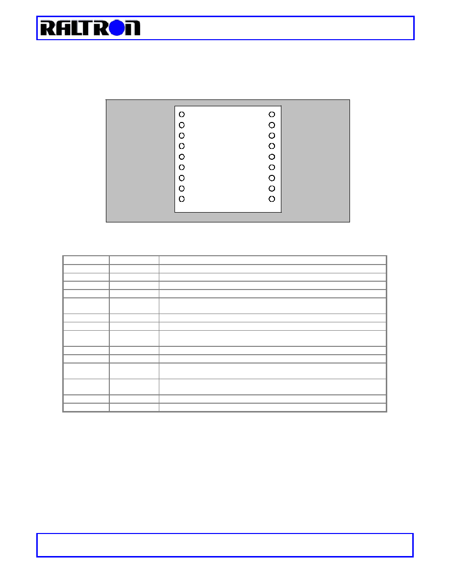
PIN ASSIGNMENT
On the picture below it is shown the pin-out for the SY01-S3. The design is done in such a way that is can support
basically any other pin-out without changes in the hardware. For other pin-out requirement please contact the Raltron.
Figure 4 ≠ Bottom view
Pin #
Name
Description
1
HOLDOVER
Holdover Signal -> the output is high when the unit is in holdover mode
2
REF 1
Reference 1 Signal -> the output is high when the unit is using the reference 1
3
REF 2
Reference 2 Signal -> the output is high when the unit is using the reference 2
4
FREERUN
Free-run Signal -> the output is high when the unit is in the free run mode
6
ALARM OUT
Alarm signal -> the output is high when there is an alarm in the module, alarm
condition is during free-run mode, holdover mode,
7
CNT 1
Control Input 1 -> the external input for selecting mode of the unit ≠ see table.
8
CNT 2
Control Input 2 -> the external input for selecting mode of the unit ≠ see table.
9
PLL UNLOCK
PLL Unlocked Signal -> the output is high when the unit is not locked to any of the
references
5,10,12,14,16
GND
Ground
18
+5V
Positive Voltage Supply
11
OUT
Synchronized Output -> the output of the synchronized signal, for frequency
range see table below.
13
OPT OUT
Optional Output -> the secondary output of the synchronized signal, for frequency
range see table below.
17
EX REF 1
External Reference 1 Input -> the input signal from reference 1
15
EX REF 2
External Reference 2 Input -> the input signal from reference 2
For other pin-out configurations contact the factory!
18
17
16
15
14
13
12
11
10
1
2
3
4
5
6
7
8
9
+5V
EX REF1
GND
EX REF 2
GND
OPT OUT
GND
OUT
GND
HOLDOVER
REF 1
REF2
FREERUN
GND
ALARM OUT
CNT 1
CNT 2
PLL UNLOCK