Preliminary: The specifications of this device are subject to change without notice. Please contact your
nearest Renesas Technology's Sales Dept. regarding specifications.
Rev.0.02, Sep.15.2004, page 1 of 89
HB28K032MM3/HB28K032RM3
HB28L064MM3/HB28L064RM3
HB28J128MM3/HB28J128RM3
HB28J256MM3/HB28J256RM3
HB28J512MM3
MultiMediaCard
32 MByte/64 MByte/128 MByte/256 MByte/512 MByte
REJ03C0178-0002
Preliminary
Rev.0.02
Sep.15.2004
Description
These Renesas MultiMediaCard
s, HB28K032MM3, HB28K032RM3, HB28L064MM3,
HB28L064RM3, HB28J128MM3, HB28J128RM3, HB28J256MM3, HB28J256RM3 and HB28J512MM3
are highly integrated flash memories with serial and random access capability. It is accessible via a
dedicated serial interface optimized for fast and reliable data transmission. This interface allows several
cards to be stacked by through connecting their peripheral contacts. These Renesas MultiMediaCards are
fully compatible to a new consumer standard, called the MultiMediaCard system standard defined in the
MultiMediaCard system specification [1]. The MultiMediaCard system is a new mass-storage system
based on innovations in semiconductor technology. It has been developed to provide an inexpensive,
mechanically robust storage medium in card form for multimedia consumer applications. MultiMediaCard
allows the design of inexpensive players and drives without moving parts. A low power consumption and
a wide supply voltage range favor mobile, battery-powered applications such as audio players, organizers,
palmtops, electronic books, encyclopedia and dictionaries. Using very effective data compression schemes
such as MPEG, the MultiMediaCard will deliver enough capacity for all kinds of multimedia data:
software/programs, text, music, speech, images, video etc.
Notes: 1. MultiMediaCard
is a trademark of Infineon Technologies AG.
2. These products are designed and manufactured for retail sale only. Therefore, please contact
Renesas Technology's Sales Dept. before using these products in other circumstances.
3. In case that these products are proved to have any defects in manufacturing attributable to
Renesas Technology Corp., the defective products can be returned and exchanged for
replacements, but Renesas Technology Corp. assumes no responsibility other than exchange.
Please contact Renesas Technology's Sales Dept. for further details.

HB28K032/L064/J128/J256/J512MM3, HB28K032/L064/J128/J256RM3
Rev.0.02, Sep.15.2004, page 2 of 89
Features
∑
MultiMediaCard
line up:
Model Memory
capacity
Outline
*
1
HB28K032MM3
32 MByte
Full size
HB28K032RM3
Reduced
size
HB28L064MM3
64 MByte
Full size
HB28L064RM3
Reduced
size
HB28J128MM3
128 MByte
Full size
HB28J128RM3
Reduced
size
HB28J256MM3
256 MByte
Full size
HB28J256RM3
Reduced
size
HB28J512MM3
512 MByte
Full size
Note: 1. Refer to Chapter "Physical Outline".
∑
On card error correction
∑
MultiMediaCard system standard compatibility
System specification version 3.3 compliant
SPI mode supports the single and multiple block read and write operations.
Block and partial block read supported (Command classes 2)
Stream read supported (Command class 1)
Block write and erase supported (Command classes 4 and 5)
Group write protection (Command classes 6)
Stream write supported (Command classes 3)
Password data access protection
Small erase block size of 8 KBytes
Read block size programmable between 1 and 2048 bytes
V
CC
= 2.7 V to 3.6 V operation voltage range (V
CC
= 2.0 V to 3.6 V for the interface)
No external programming voltage required
Damage free powered card insertion and removal (no operation)
4kV ESD protection (Contact Pads)
∑
High speed serial interface with random access
Up to 10 stacked card (at 20 MHz, V
CC
= 2.7 to 3.6 V)
Access time: 300
µ
s (typ) (at 20 MHz, V
CC
= 2.7 to 3.6 V)
∑
Low power dissipation
High speed: 288 mW (max) (at 20 MHz, V
CC
= 3.6 V)
∑
Small size
Full size (24
◊
32
◊
1.4 mm
3
): 32-512 MByte
Reduced size (24
◊
18
◊
1.4 mm
3
): 32-256 MByte
HB28K032/L064/J128/J256/J512MM3, HB28K032/L064/J128/J256RM3
Rev.0.02, Sep.15.2004, page 3 of 89
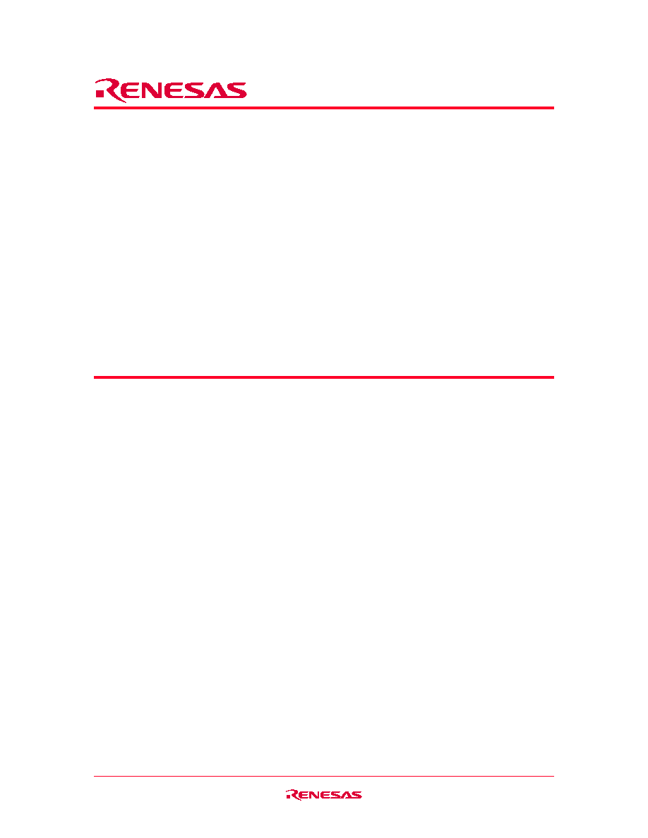
Block Diagram
1
2
3
4
V
PP
Generator
5
6
7
Internal clock
Interface
CID[127:0]
OCR[31:0]
Flash control
Core control
CSD[127:0]
RCA[15:0]
CMD
P
o
w
er on reset unit
Register
set
DA
T
V
CC
CS CMD/DI
DAT/DO
CLK/SCLK
Interface driver
Memory core
All units in these Renesas MultiMediaCards are clocked by an internal clock generator. The Interface
driver unit synchronizes the DAT and CMD signals from external CLK to the internal used clock signal.
The card is controlled by the three line MultiMediaCard interface containing the signals: CMD, CLK,
DAT (refer to Chapter "Interfaces"). For the identification of the MultiMediaCard in a stack of
MultiMediaCards, a card identification register (CID) and a relative card address register (RCA) are
foreseen. An additional register contains different types of operation parameters. This register is called
card specific data register (CSD). The communication using the MultiMediaCard lines to access either the
memory field or the registers is defined by the MultiMediaCard standard (refer to Chapter
"Communication"). The card has its own power on detection unit. No additional master reset signal is
required to setup the card after power on. It is protected against short circuit during insertion and removal
while the MultiMediaCard system is powered up (refer to Chapter "Power Supply"). No external
programming voltage supply is required. The programming voltage is generated on card.
These Renesas MultiMediaCards support a second interface operation mode the SPI interface mode. The
SPI mode is activated if the CS signal is asserted (negative) during the reception of the reset command
(CMD0) (refer to Chapter "SPI Communication").

HB28K032/L064/J128/J256/J512MM3, HB28K032/L064/J128/J256RM3
Rev.0.02, Sep.15.2004, page 4 of 89
Interface
These Renesas MultiMediaCards' interface can operate in two different modes:
∑
MultiMediaCard mode
∑
SPI mode
Both modes are using the same pins. The default mode is the MultiMediaCard mode. The SPI mode is
selected by activating (= 0) the CS signal (Pin1) and sending the CMD0.
MultiMediaCard Mode
In the MultiMediaCard mode, all data is transferred over a minimal number of lines:
∑
CLK: with each cycle of this signal a one-bit transfer on the command and data lines is done. The
frequency may vary between zero and the maximum clock frequency. The MultiMediaCard bus
master is free to generate these cycles without restrictions in the range of 0 to 20 MHz.
∑
CMD: is a bidirectional command channel used for card initialization and data transfer commands.
The CMD signal has two operation modes: open drain for initialization mode and push pull for fast
command transfer. Commands are sent from the MultiMediaCard bus master to the MultiMediaCard
and responses vice versa.
∑
DAT: is a bidirectional data channel with a width of one line. The DAT signal of the MultiMediaCard
operates in push pull mode.
∑
RSV: is pulled up with resistor (2 M
typ) in the MultiMediaCard. The external pull-up resistor
should be recommended if the system requires.
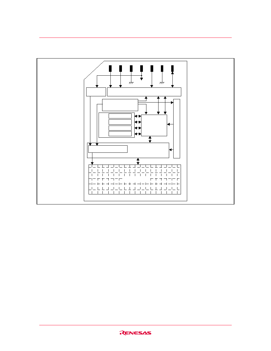
Interf
ace dr
iv
er
MultiMediaCard Host
ROD
RDAT
RCMD
1 2 3 4 5 6 7
MultiMediaCard
CMD
CLK
DAT
MultiMediaCard Mode Interface
All MultiMediaCards are connected directly to the lines of the MultiMediaCard bus. The following table
defines the card contacts.
HB28K032/L064/J128/J256/J512MM3, HB28K032/L064/J128/J256RM3
Rev.0.02, Sep.15.2004, page 5 of 89
MultiMediaCard Mode Pad Definition
Pin No.
Name
Type
*
1
Description
1 RSV
NC
No
connection
2 CMD
I/O/PP/OD
Command/Response
3 V
SS1
S
Ground
4 V
CC
S Power
supply
5 CLK
I Clock
6 V
SS2
S
Ground
7 DAT
I/O/PP
Data
Note: 1. S: power supply; I: input; O: output; PP: push-pull; OD: open-drain; NC: No connection or V
IH
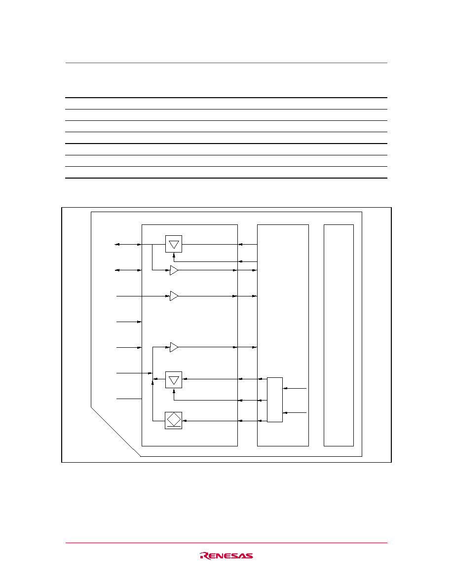
MultiMediaCard interf
ace controller
1 2 3 4 5 6 7
Memor
y core interf
ace
OD/PP
enable
enable
Interface driver
DAT
CMD
V
SS1
V
CC
CLK
V
SS2
RSV
MultiMediaCard Mode I/O-drivers