Rev.1.00, Jun.03.2003, page 1 of 16
HD74SSTV16857B
1:1 14-bit SSTL_2 Registered Buffer
REJ03D0023≠0100Z
(Previous ADE-205-712 (Z))
Rev.1.00
Jun.03.2003
Description
The HD74SSTV16857B is a 14-bit registered buffer designed for 2.3 V to 2.7 V Vcc operation and
LVCMOS reset (
RESET) input / SSTL_2 data (D) inputs and CLK input.
Data flow from D to Q is controlled by differential clock pins (CLK,
CLK) and the RESET. Data is
triggered on the positive edge of the positive clock (CLK), and the negative clock (
CLK) must be used to
maintain noise margins. When
RESET is low, all registers are reset and all outputs are low.
To ensure defined outputs from the register before a stable clock has been supplied,
RESET must be held in
the low state during power up.
Features
∑
Supports LVCMOS reset (
RESET) input / SSTL_2 data (D) inputs and CLK input
∑
Differential SSTL_2 (Stub series terminated logic) CLK signal
∑
Flow through architecture optimizes PCB layout
∑
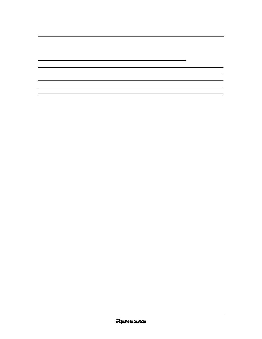
Ordering Information
Part Name
Package Type
Package Code Package
Abbreviation
Taping
Abbreviation (Quantity)
HD74SSTV16857BTEL
TSSOP-48 pin
TTP-48DBV
T
EL (1,000 pcs / Reel)
HD74SSTV16857BNEL
TVSOP-48 pin
TTP-48DEV
N
EL (1,000 pcs / Reel)
Note: Please consult the sales office for the above package availability.
HD74SSTV16857B
Rev.1.00, Jun.03.2003, page 2 of 16
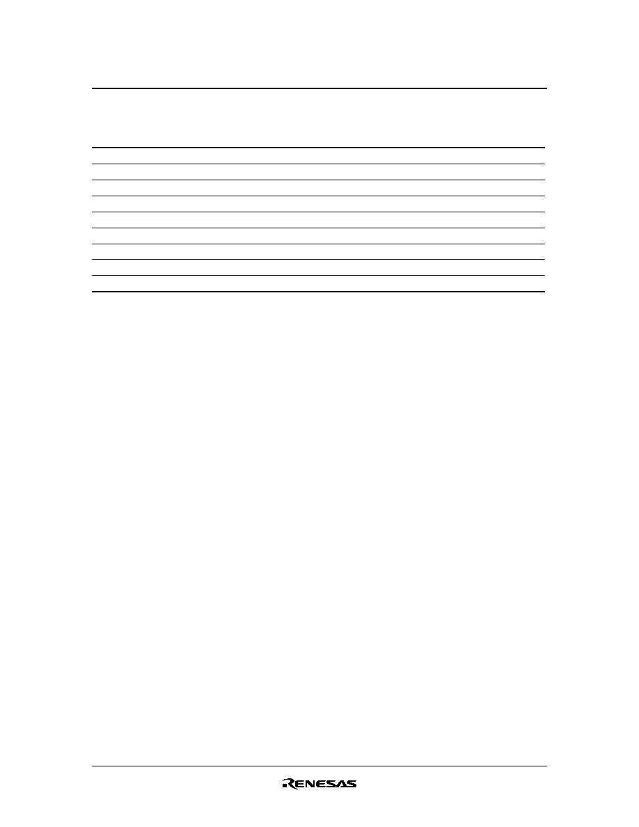
Function Table
Inputs
RESET
CLK
CLK
D
Output Q
L
X
X
X
L
H
H
H
H
L
L
H
L or H
H or L
X
Q
0
*1
H :
High level
L :
Low level
X :
Immaterial
:
Low to high transition
:
High to low transition
Note:
1. Output level before the indicated steady state input conditions were established.

HD74SSTV16857B
Rev.1.00, Jun.03.2003, page 3 of 16
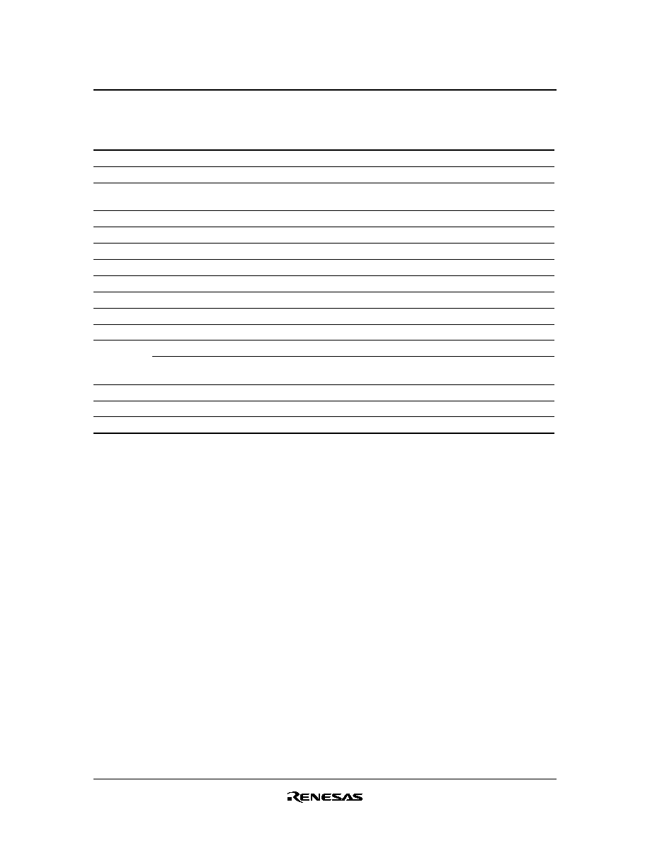
Pin Arrangement
(Top view)
1
2
3
4
5
6
7
8
9
10
GND
GND
GND
GND
GND
11
12
13
14
15
16
17
18
19
20
21
22
23
24
25
26
27
28
29
30
31
32
33
34
35
36
37
38
39
40
41
42
43
44
45
46
47
48
Q2
Q1
Q7
Q6
Q4
Q5
Q3
Q9
Q8
Q14
Q13
Q12
Q11
Q10
D14
D13
GND
D12
D11
RESET
GND
D9
D8
CLK
D10
D3
D4
D5
D6
D7
D2
D1
GND
V
DDQ
V
DDQ
V
DDQ
V
DDQ
V
DDQ
V
CC
V
REF
CLK
V
CC
V
CC
HD74SSTV16857B
Rev.1.00, Jun.03.2003, page 4 of 16
Absolute Maximum Ratings
Item
Symbol
Ratings
Unit
Conditions
Supply voltage
V
CC
or V
DDQ
≠0.5 to 3.6
V
Input voltage
*1
V
I
≠0.5 to V
DDQ
+0.5
V
Output voltage
*1, 2
V
O
≠0.5 to V
DDQ
+0.5
V
Input clamp current
I
IK
±50
mA
V
I
< 0 or V
I
> V
CC
Output clamp current
I
OK
±50
mA
V
O
< 0 or V
O
> V
DDQ
Continuous output current
I
O
±50
mA
V
O
= 0 to V
DDQ
V
CC
, V
DDQ
or GND current / pin
I
CC
, I
DDQ
or I
GND
±100
mA
Package thermal impedance
JA
115
∞C / W
TSSOP
Storage temperature
Tstg
≠65 to +150
∞C
Notes:
Stresses beyond those listed under "absolute maximum ratings" may cause permanent damage
to the device. These are stress ratings only, and functional operation of the device at these or
any other conditions beyond those indicated under "recommended operating conditions" is not
implied. Exposure to absolute maximum rated conditions for extended periods may affect device
reliability.
1. The input and output negative voltage ratings may be exceeded if the input and output clamp
current ratings are observed.
2. This current will flow only when the output is in the high state and V
O
> V
DDQ
.
HD74SSTV16857B
Rev.1.00, Jun.03.2003, page 5 of 16
Recommended Operating Conditions
Item
Symbol Min
Typ
Max
Unit Conditions
Supply voltage
V
CC
V
DDQ
2.5
2.7
V
Output supply voltage
V
DDQ
2.3
2.5
2.7
V
Reference voltage
V
REF
1.15
1.25
1.35
V
V
REF
= 0.5
◊
V
DDQ
Termination voltage
V
TT
V
REF
≠40 mV V
REF
V
REF
+40 mV
V
Input voltage
V
I
0
--
V
CC
V
AC high level input voltage
V
IH
V
REF
+310 mV --
--
V
D
AC low level input voltage
V
IL
--
--
V
REF
≠310 mV V
D
DC high level input voltage
V
IH
V
REF
+150 mV --
--
V
D
DC low level input voltage
V
IL
--
--
V
REF
≠150 mV V
D
High level input voltage
V
IH
1.7
--
V
DDQ
+0.3
V
RESET
Low level input voltage
V
IL
≠0.3
--
0.7
V
RESET
(Common mode range)
V
CMR
0.97
--
1.53
V
CLK,
CLK
Differential
input voltage
(Minimum peak to
peak input)
V
PP
360
--
--
mV CLK,
CLK
High level output current
I
OH
--
--
≠20
mA
Low level output current
I
OL
--
--
20
mA
Operating temperature
Ta
0
--
70
∞C
Note: The
RESET
input of the device must be held at V
DDQ
or GND to ensure proper device operation.
The differential inputs must not be floating, unless
RESET
is low.