Document Outline
- ˛ˇ
- ˛ˇ
- ˛ˇ
- ˛ˇ
- ˛ˇ
- ˛ˇ
- ˛ˇ
- ˛ˇ
- ˛ˇ
- ˛ˇ
- ˛ˇ
- ˛ˇ
- ˛ˇ
- ˛ˇ
- ˛ˇ
- ˛ˇ
- ˛ˇ
- ˛ˇ
- ˛ˇ
- ˛ˇ
- ˛ˇ
- ˛ˇ
- ˛ˇ
- ˛ˇ
- ˛ˇ
- ˛ˇ
- ˛ˇ
- ˛ˇ
- ˛ˇ

Regarding the change of names mentioned in the document, such as Mitsubishi
Electric and Mitsubishi XX, to Renesas Technology Corp.
The semiconductor operations of Hitachi and Mitsubishi Electric were transferred to Renesas
Technology Corporation on April 1st 2003. These operations include microcomputer, logic, analog
and discrete devices, and memory chips other than DRAMs (flash memory, SRAMs etc.)
Accordingly, although Mitsubishi Electric, Mitsubishi Electric Corporation, Mitsubishi
Semiconductors, and other Mitsubishi brand names are mentioned in the document, these names
have in fact all been changed to Renesas Technology Corp. Thank you for your understanding.
Except for our corporate trademark, logo and corporate statement, no changes whatsoever have been
made to the contents of the document, and these changes do not constitute any alteration to the
contents of the document itself.
Note : Mitsubishi Electric will continue the business operations of high frequency & optical devices
and power devices.
Renesas Technology Corp.
Customer Support Dept.
April 1, 2003
To all our customers

M32C/83 GROUP
DATA SHEET
REV.1.02
Specifications written in this manual are believed to be accurate, but are not guar-
anteed to be entirely free of error.
Specifications in this manual may be changed for functional or performance im-
provements. Please make sure your manual is the latest edition.
Mitsubishi Electric proprietary information

Under
development
Preliminary Specifications REV.1.02
Specifications in this manual are tentative and subject to change.
Mitsubishi Microcomputers
M32C/83 group
SINGLE-CHIP 16/32-BIT CMOS MICROCOMPUTER
Overview
1
Overview
The M32C/83 is single-chip microcomputer that utilizes high-performance silicon gate CMOS technology
with the M32C/80 series CPU core. The M32C/83 group is available in the 144-pin and 100-pin plastic
molded QFP/LQFP package.
With 16-Mbyte address memory space, this microcomputer combines advanced instructions manipulation
capabilities to process complex instructions by less bytes and execute instructions at higher speed.
It incorporates a multiplier and DMAC adequate to office automation, communication devices and industrial
equipments and other high-speed processing applications.
Applications
Audio, cameras, office equipment, communications equipment, portable equipment, etc.
Specifications written in this manual are believed to be accurate, but are
not guaranteed to be entirely free of error.
Specifications in this manual may be changed for functional or performance
improvements. Please make sure your manual is the latest edition.
----- Table of Contents -----
Three-phase Motor Control Timer Functions .. 163
Serial I/O ..................................................174
CAN Module .............................................225
Intelligent I/O ............................................264
A-D Converter ..........................................338
D-A Converter ..........................................355
CRC Calculation .......................................358
X-Y Conversion ........................................360
DRAMC ....................................................363
Programmable I/O Ports ..........................370
Usage Precaution .....................................394
Flash Memory Version .............................401
Electrical Characteristics ..........................427
Register Index ..........................................464
Overview ..................................................1
Memory ....................................................19
Central Processing Unit (CPU) ................20
Reset .......................................................23
SFR ..........................................................26
Processor Mode .......................................48
Bus ...........................................................52
System Clock ...........................................65
Protection .................................................87
Interrupts ..................................................88
Watchdog Timer .......................................112
DMAC .......................................................115
DMAC II ....................................................126
Timer ........................................................135
Under
development
Preliminary Specifications REV.1.02
Specifications in this manual are tentative and subject to change.
Mitsubishi Microcomputers
M32C/83 group
SINGLE-CHIP 16/32-BIT CMOS MICROCOMPUTER
Overview
2
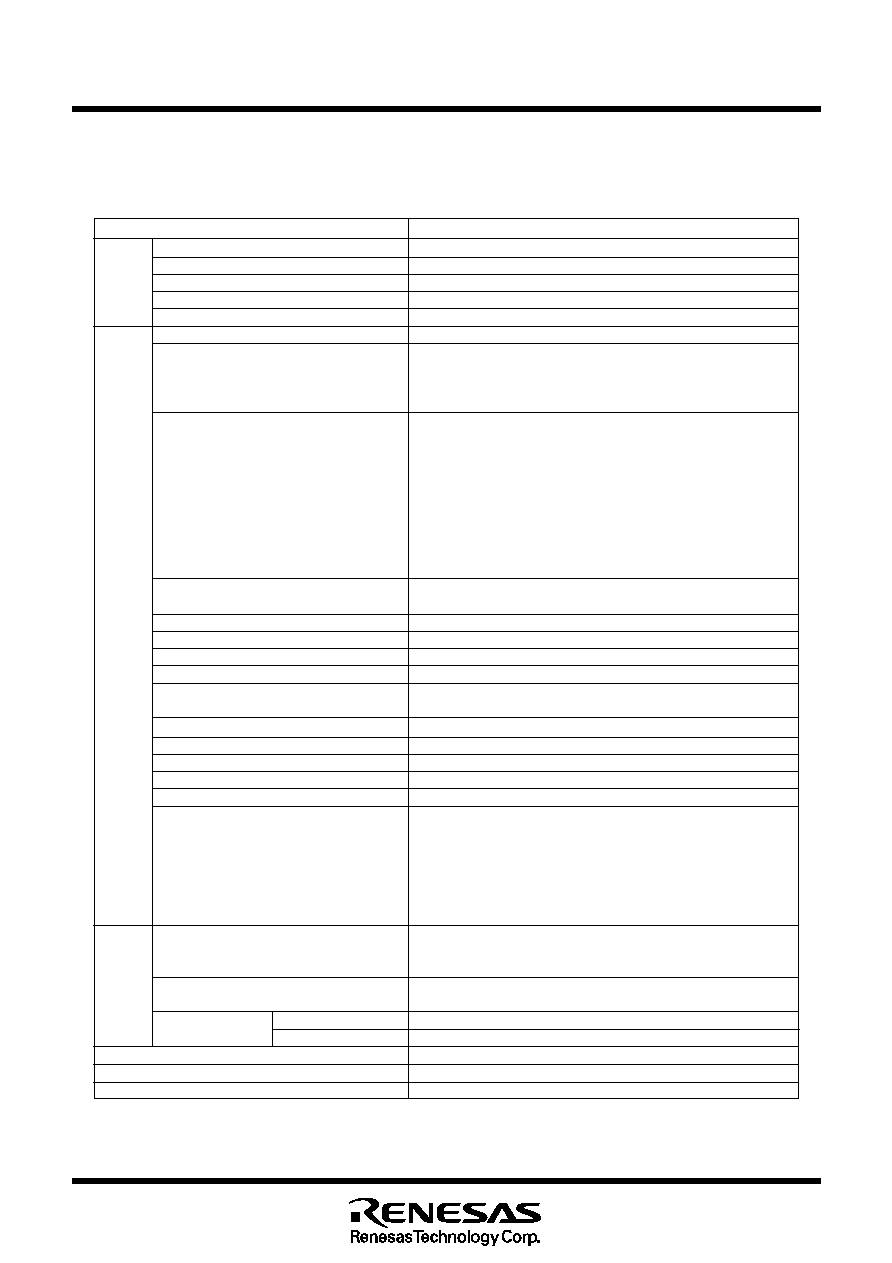
Performance Outline
Tables 1.1.1 and 1.1.2 list performance outline of the M32C/83 group.
Table 1.1.1. M32C/83 Group Performance (144-Pin Package)
Item
Performance
CPU
Basic instructions
108 instructions
Shortest instruction execution time
33 ns (f(X
IN
)=30MHz)
Operation mode
Single-chip, memory expansion and microprocessor modes
Memory space
16M bytes
Memory capacity
See Table 1.1.3.
Peripheral I/O port
124 pins (P0 to P15, P8
5
is used as an input port)
function Multifunction timer
Output
16 bits x 5 channels (TA0, TA1, TA2, TA3, TA4)
Input
16 bits x 6 channels (TB0, TB1, TB2, TB3, TB4, TB5)
Three-phase motor control output
1 circuit
Intelligent I/O
4 groups
Time measurement function
12 channels (group 0: 8 channels, group1: 4 channels)
Waveform generation function
28 channels (group 0: 4 channels, group1,2,3: 8 channels each)
Bit modulation PWM
16 channels (group 2,3: 8 channels each)
Real-time port
16 channels (group 2,3: 8 channels each)
Communication function
∑ Clock synchronous serial I/O, UART: 2 channels (group 0 and 1)
∑ HDLC data processing : 2 channels (group 0 and 1)
∑ Clock synchronous variable length serial I/O:1 channel (group 2)
∑ IE bus
1
: 1 channel (group 2)
∑ 8-bit or 16-bit clock synchronous serial I/O : 1 channel (group 3)
Serial I/O
5 channels (UART0 to UART4)
Clock synchronous,Clock asynchronous,IE Bus
1
, I
2
C Bus
2
CAN module
1 channel, supporting CAN 2.0B specification
A-D converter
10-bit A-D x 2 circuits (standard 18 inputs, maximum 34 inputs)
D-A converter
8-bit D-A x 2 circuits
DMAC
4 channels
DMAC II
Activated by all relocatable vector interrupt factors
Immediate transfer, arithmetic transfer and chain transfer functions
DRAMC
_______
_______
CAS-before-RAS refresh, self-refresh, EDO, FP
CRC calculation circuit
CRC-CCITT
X-Y converter
16 bits X 16 bits
Watchdog timer
15 bits x 1 channel (with prescaler)
Interrupt
42 internal and 8 external sources, 5 software sources, interrupt priority level 7
Clock generation circuit
4 circuits
∑ Main clock generation circuit
∑ Sub clock generation circuit
The above circuits include an internal feedback resistance and
external ceramic resonator/crystal oscillator.
∑ Ring oscillator (for the main clock oscillator stop detect function)
∑ PLL frequency synthesizer
Electric
Supply voltage
4.2 to 5.5V (f(X
IN
)=30MHz, VDC on)
charact-
3.0 to 5.5V (f(X
IN
)=20MHz, VDC on)
eristics
3.0 to 3.6V (f(X
IN
)=20MHz, VDC off)
Power consumption
38mA (f(X
IN
)=30MHz with no wait,Vcc=5V)
26mA (f(X
IN
)=20MHz with no wait,Vcc=3.3V)
I/O characteristics
I/O withstand voltage Vcc
I/O current
5mA
Operating ambient temperature
≠20 to 85
o
C, ≠40 to 85
o
C
Device configuration
CMOS high performance silicon gate
Package
144-pin plastic mold QFP
Notes :
1. IE Bus is a trademark of NEC Corporation.
2. I
2
C Bus is a trademark of Koninklijke Philips Electronics N. V.
Under
development
Preliminary Specifications REV.1.02
Specifications in this manual are tentative and subject to change.
Mitsubishi Microcomputers
M32C/83 group
SINGLE-CHIP 16/32-BIT CMOS MICROCOMPUTER
Overview
3
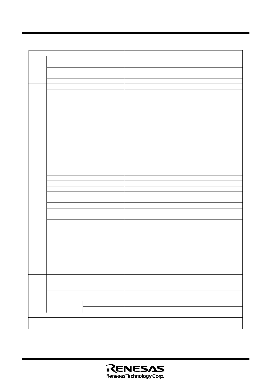
Table 1.1.2. M32C/83 Group Performance (100-Pin Package)
Item
Performance
CPU
Basic instructions
108 instructions
Shortest instruction execution time
33 ns (f(X
IN
)=30MHz)
Operation mode
Single-chip, memory expansion and microprocessor modes
Memory space
16M bytes
Memory capacity
See Table 1.1.3.
Peripheral I/O port
88 pins (P0 to P10, P8
5
is used as an input port)
function Multifunction timer
Output
16 bits x 5 channels (TA0, TA1, TA2, TA3, TA4)
Input
16 bits x 6 channels (TB0, TB1, TB2, TB3, TB4, TB5)
Three-phase motor control output
1 circuit
Intelligent I/O
4 groups
Time measurement function
5 channels (group 0: 3 channels, group1: 2 channels)
Waveform generation function
10 channels (group 0,3: 2 channels each, group1,2: 3 channels each)
Bit modulation PWM
5 channels (group 2 : 3 channels, group 3 : 2 channels)
Real time port
5 channels (group 2 : 3 channels, group 3 : 2 channels)
Communication function
∑ Clock synchronous serial I/O, UART: 2 channels (group 0 and 1)
∑ HDLC data processing : 2 channels (group 0 and 1)
∑ Clock synchronous variable length serial I/O:1 channel (group 2)
∑ IE bus
1
: 1 channel (group 2)
Serial I/O
5 channels (UART0 to UART4)
Clock synchronous,Clock asynchronous,IE Bus
1
, I
2
C Bus
2
CAN module
1 channel, supporting CAN 2.0B specification
A-D converter
10-bit A-Dx 2 circuits (standard 10 inputs, maximum 26 inputs)
D-A converter
8-bit D-A x 2 circuits
DMAC
4 channels
DMAC II
Activated by all relocatable vector interrupt factors
Immediate transfer, arithmetic transfer and chain transfer functions
DRAMC
_______
_______
CAS-before-RAS refresh, self-refresh, EDO, FP
CRC calculation circuit
CRC-CCITT
X-Y converter
16 bits X 16 bits
Watchdog timer
15 bits x 1 channel (with prescaler)
Interrupt
42 internal and 8 external sources, 5 software sources,
interrupt priority level 7
Clock generation circuit
4 circuits
∑ Main clock generation circuit
∑ Sub clock generation circuit
The above circuits include an internal feedback resistance and
external ceramic resonator/crystal oscillator.
∑ Ring oscillator (for the main clock oscillator stop detect function)
∑ PLL frequency synthesizer
Electric
Supply voltage
4.2 to 5.5V (f(X
IN
)=30MHz, VDC on)
charac-
3.0 to 5.5V (f(X
IN
)=20MHz, VDC on)
teristics
3.0 to 3.6V (f(X
IN
)=20MHz, VDC off)
Power consumption
38mA (f(X
IN
)=30MHz with no wait,Vcc=5V)
26mA (f(X
IN
)=20MHz with no wait,Vcc=3.3V)
I/O characteristics
I/O withstand voltage Vcc
I/O current
5mA
Operating ambient temperature
≠20 to 85
o
C, ≠40 to 85
o
C
Device configuration
CMOS high performance silicon gate
Package
100-pin plastic mold QFP
Notes :
1. IE Bus is a trademark of NEC Corporation.
2. I
2
C Bus is a trademark of Koninklijke Philips Electronics N. V.