Æ
RF Monolithics, Inc.
Phone: (972) 233-2903
Fax: (972) 387-8148
E-mail: info@rfm.com
Page 1 of 2
RFM Europe
Phone: 44 1963 251383
Fax: 44 1963 251510
http://www.rfm.com
©1999 by RF Monolithics, Inc. The stylized RFM logo are registered trademarks of RF Monolithics, Inc.
RF1304-062702
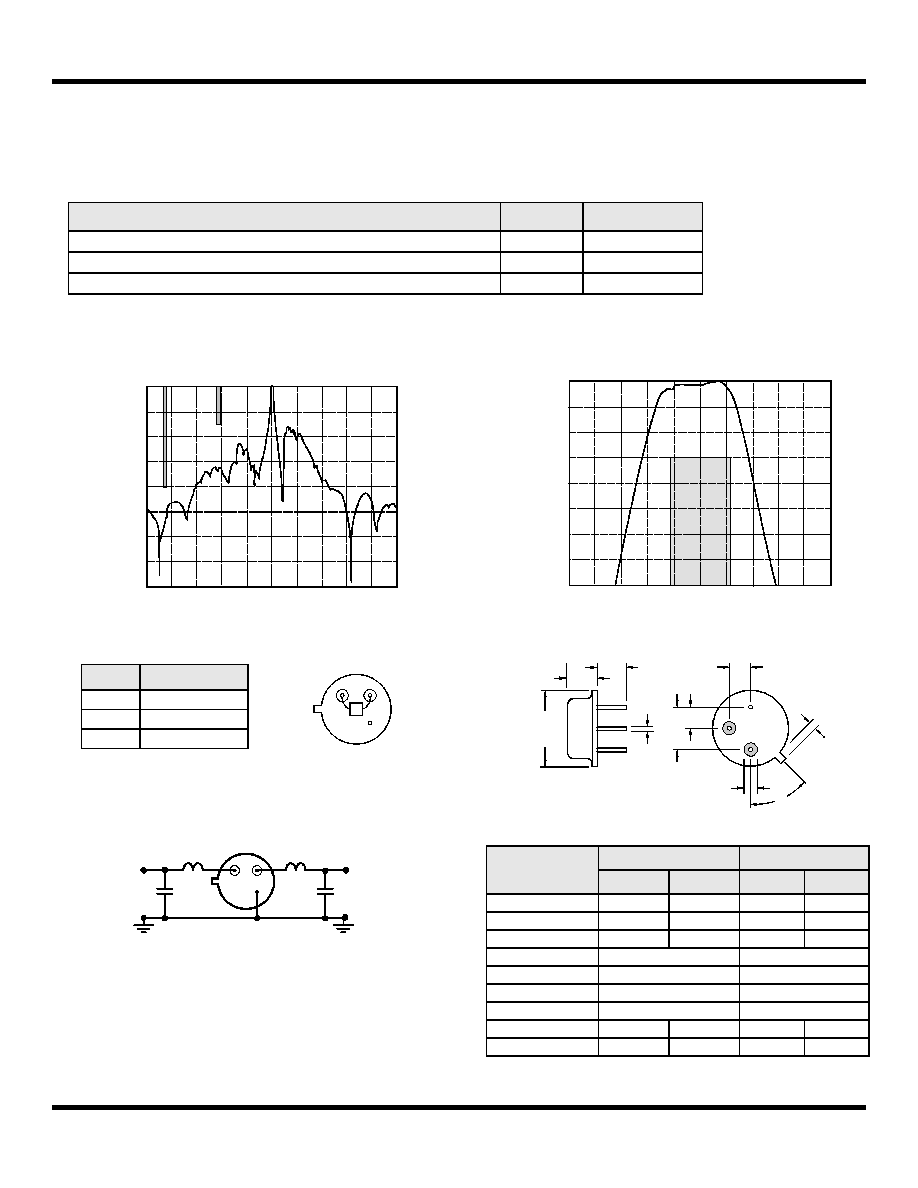
Electrical Characteristics
Characteristic
Sym
Notes
Minimum
Typical
Maximum
Units
Nominal Frequency
f
C
2, 4, 5, 6
391.250
MHz
Insertion Loss
IL
3, 4, 7
4.0
dB
4 dB Passband
BW
3
2, 3, 4, 7
±30
kHz
3 dB Reject Band
BW
3
2, 3, 4, 7
kHz
Rejection
at f
C
±1.50 MHz
4
10
dB
at f
C
±6.0 MHz
25
at f
C
±50 MHz
Temperature
Operating Case Temperature
T
C
3, 7, 8
-40
+85
∞C
Turnover Temperature
T
O
15
25
40
∞C
Turnover Frequency
f
O
f
C
MHz
Frequency Temperature Coefficient
FTC
0.032
ppm/∞C
2
Frequency Aging
Absolute Value during the First Year
IfAI
3
10
ppm/yr
External Impedance
Series Inductance
L
1, 7
22
nH
Shunt Capacitance
C
5-18
pF
Lid Symbolization (in addition to Lot and/or Date Codes)
RFM RF1304
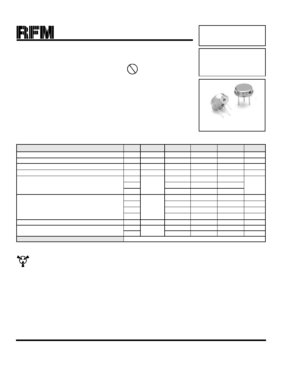
TO39-3 Case
∑
Ideal Front-End Filter for European Wireless Receivers
∑
Low-Loss, Coupled-Resonator Quartz Design
∑
Simple External Impedance Matching
∑
Rugged TO39 Hermetic Package
∑
Complies with Directive 2002/95/EC (RoHS)
The RF1304 is a low-loss, compact and economical surface-acoustic-wave (SAW) filter designed to provide
front-end selectivity in 391.250 MHz receivers. Typical applications of these FSK receivers are wireless
remote-control and security devices operating in Europe.
RFM's advanced SAW design and fabrication technology is utilized to achieve high performance and very low
loss with simple external impedance matching (not included). Quartz construction provides excellent frequen-
cy stability over a wide temperature range.
391.250 MHz
SAW Filter
RF1304
CAUTION: Electrostatic Sensitive Device. Observe precautions for handling.
Notes:
1. Typical test circuit is shown for TO-39 RF filters.
2. Passband and reject bands are specified in reference to f
C
.
3. All characteristics are specified over the operating temperature range and typical aging for 10 years.
4. Unless noted otherwise, all measurements are made with the filter installed in the specified test fixture. Note that insertion loss, bandwidth, and pass-
band shape are dependent on the impedance matching component values and quality. Demonstration circuits are available for confirmation of device
performance.
5. One or more of the following U.S. Patents apply: 4,454,488; 4,616,197; and other pending.
6. All equipment designs utilizing this product must be approved by the appropriate government agency prior to manufacture or sale.
7. The design, manufacturing process, and specifications of this device are subject to change without notice.
8. The turnover temperature, T
O
, is the temperature of maximum (or turnover) frequency, f
o
. The nominal frequency at any case temperature, T
C
, out-
side the operating temperature range may be calculated from: f = f
o
[1 - FTC (T
O
- T
C
)
2
].
Pb