Æ
RF Monolithics, Inc.
Phone: (972) 233-2903
Fax: (972) 387-9148
E-mail: info@rfm.com
Page 1 of 2
RFM Europe
Phone: 44 1963 251383
Fax: 44 1963 251510
http://www.rfm.com
©1999 by RF Monolithics, Inc. The stylized RFM logo are registered trademarks of RF Monolithics, Inc.
RP1104-110499
Electrical Characteristics
Characteristic
Sym
Notes
Minimum
Typical
Maximum
Units
Center Frequency
Absolute Frequency
f
C
2, 3, 4, 5,
824.100
824.400
MHz
Tolerance from 824.250 MHz
f
C
±150
kHz
Insertion Loss
IL
2, 5, 6
9.0
9.5
dB
Quality Factor
Unloaded Q
Q
U
5, 6, 7
7,100
50
Loaded Q
Q
L
4,500
Temperature Stability
Turnover Temperature
T
O
6, 7, 8
66
81
96
∞C
Turnover Frequency
f
O
f
C
+96
kHz
Frequency Temp. Coefficient
FTC
0.037
ppm/∞C
2
Frequency Aging
Absolute Value during First Year
|f
A
|
6
10
ppm/yr
DC Insulation Resistance between Any Two Pins
5
1.0
M
RF Equivalent RLC
Motional Resistance
R
M
5, 7, 9
182
199
Motional Inductance
L
M
248.091
µH
Motional Capacitance
C
M
0.150284
fF
Shunt Static Capacitance
C
O
5, 6, 9
1.2
1.5
1.8
pF
Lid Symbolization (in addition to Lot and/or Date Codes)
RFM P1104
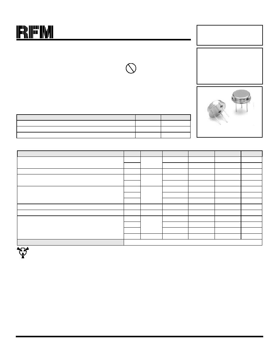
TO39-3 Case
∑
Ideal for 824 MHz Oscillators
∑
Nominal Insertion Phase Shift of 180∞ at Resonance
∑
Quartz Stability
∑
Rugged, Hermetic, Low-Profile TO39 Case
∑
Complies with Directive 2002/95/EC (RoHS)
The RP1104 is a two-port, 180∞ surface-acoustic-wave (SAW) resonator in a low-profile TO39 case. It pro-
vides reliable, fundamental-mode, quartz frequency stabilization of fixed-frequency oscillators operating at or
near 824.05 MHz. The nominal resonator frequency is higher than the nominal oscillator frequency to allow
for production frequency tuning. This SAW is designed specifically for stabilization of the second LO of CATV
convertors with channel 13 outputs for use in Taipei. In this application, the oscillator must be a modified-
Colpitts design with the SAW connected to simulate a one-port SAW.
Absolute Maximum Ratings
Rating
Value
Units
CW RF Power Dissipation (See: Typical Test Circuit)
+5
dBm
DC Voltage Between Any Two Pins (Observe ESD Precautions)
±30
VDC
Case Temperature
-40 to +85
∞C
824.25 MHz
SAW
Resonator
RP1104
CAUTION: Electrostatic Sensitive Device. Observe precautions for handling.
Notes:
1.
Frequency aging is the change in f
C
with time and is specified at +65∞C or less. Aging may exceed the specification for prolonged temperatures
above +65∞C. Typically, aging is greatest the first year after manufacture, decreasing significantly in subsequent years.
2.
The frequency f
C
is the frequency of minimum IL with the resonator in the specified test fixture in a 50
test system with VSWR
1.2:1. Typically,
f
OSCILLATOR
or f
TRANSMITTER
is less than the resonator f
C
.
3.
One or more of the following United States patents apply: 4,454,488; 4,616,197.
4.
Typically, equipment utilizing this device requires emissions testing and government approval, which is the responsibility of the equipment manufac-
turer.
5.
Unless noted otherwise, case temperature T
C
= +25∞C± 5∞C
6.
The design, manufacturing process, and specifications of this device are subject to change without notice.
7.
Derived mathematically from one or more of the following directly measured parameters: f
C
, IL, 3 dB bandwidth, f
C
versus T
C
, and C
O
.
8.
Turnover temperature, T
O
, is the temperature of maximum (or turnover) frequency, f
O
. The nominal frequency at any case temperature, T
C
, may be
calculated from: f = f
O
[1 - FTC (T
O
- T
C
)
2
]. Typically,
oscillator T
O
is 20∞ less than the specified
resonator T
O
.
9.
This equivalent RLC model approximates resonator performance near the resonant frequency and is provided for reference only. The capacitance
C
O
is the measured static (nonmotional) capacitance between either pin 1 and ground or pin 2 and ground. The measurement includes case parasitic
capacitance.
Pb
824.25 MHz SAW Resonator
RF Monolithics, Inc.
Phone: (972) 233-2903
Fax: (972) 387-9148
E-mail: info@rfm.com
Page 2 of 2
RFM Europe
Phone: 44 1963 251383
Fax: 44 1963 251510
http://www.rfm.com
©1999 by RF Monolithics, Inc. The stylized RFM logo are registered trademarks of RF Monolithics, Inc.
RP1104-110499
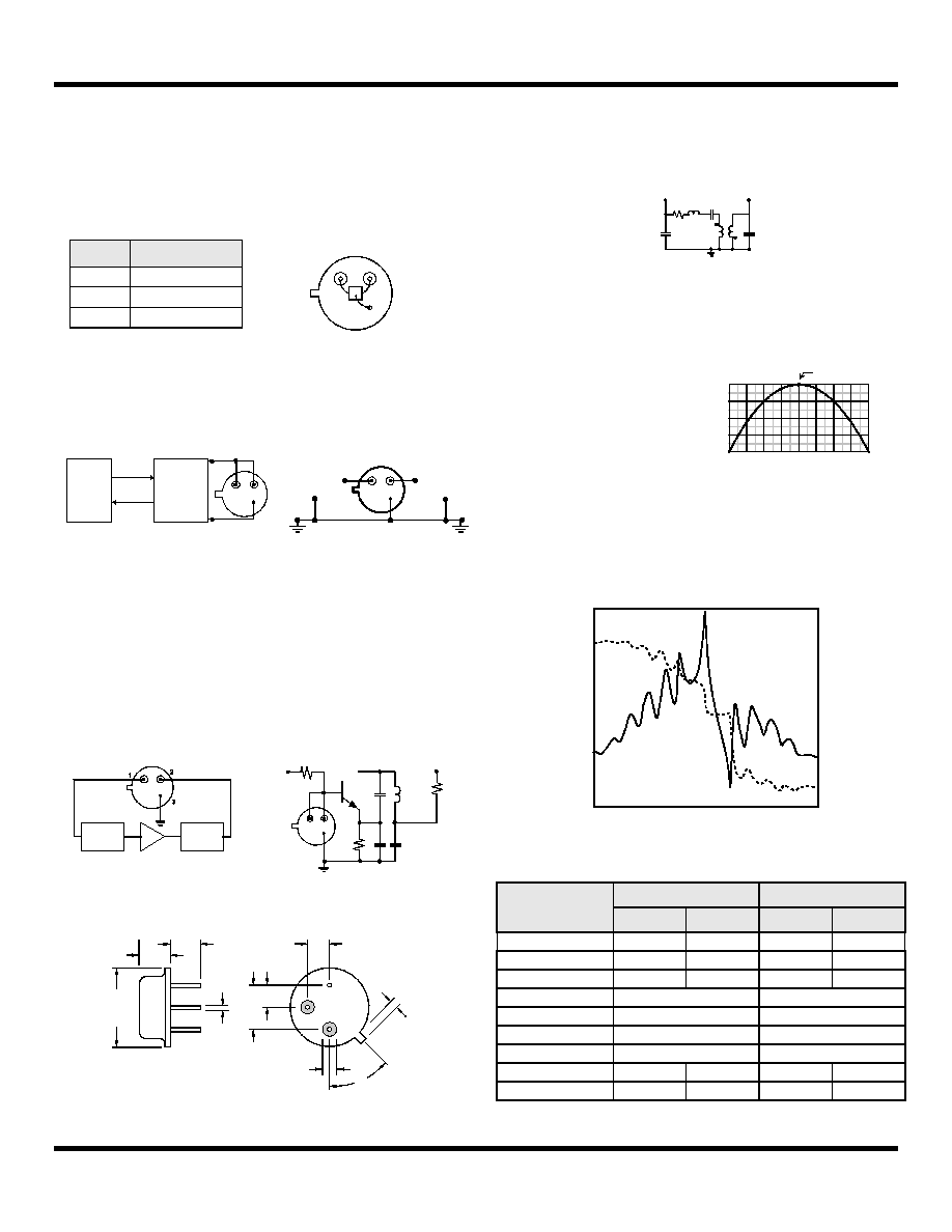
Electrical Connections
This two-port, three-terminal SAW resonator is bidirectional. However, im-
pedances and circuit board parasitics may not be symmetrical, requiring
slightly different oscillator component-matching values.
Typical Test Circuit
Typical Application Circuits
Case Design
Equivalent LC Model
Temperature Characteristics
Typical Frequency Response
Pin
Connection
1
Input or Output
2
Output or Input
3
Case Ground
Bottom View
Pin 1
Pin 2
Pin 3
50
Source at
F
C
Low-Loss
Matching
Network
50
to
Power Test
P
P
INCIDENT
INCIDENT
CW RF Power Dissipation =
-
REFLECTED
REFLECTED
P
P
1
3
2
2
3
1
From 50
Network
Analyzer
To 50
Network
Analyzer
Electrical Test
This SAW resonator can be used in oscillator or transmitter designs that
require 180∞ phase shift at resonance in a two-port configuration. One-
port resonators can be simulated, as shown, by connecting pins 1 and 2
together. However, for most low-cost consumer products, this is only
recommended for retrofit applications and not for new designs.
Phasing
& Match
Phasing
& Match
1
2
3
Conventional Two-Port Design: Simulated One-Port Design:
B
45∞
J
(2 places)
D
(3 places)
H
G
E
F
C
A
Dimensions
Millimeters
Inches
Min
Max
Min
Max
A
9.40
0.370
B
3.18
0.125
C
2.50
3.50
0.098
0.138
D
0.46 Nominal
0.018 Nominal
E
5.08 Nominal
0.200 Nominal
F
2.54 Nominal
0.100 Nominal
G
2.54 Nominal
0.100 Nominal
H
1.02
0.040
J
1.40
0.055
C
M
C o
C o
R
M
L
M
1
2
3
The following equivalent LC model is valid near resonance:
-80 -60 -40 -20
0 +20 +40 +60
0
-50
-100
-150
+80
-200
0
-50
-100
-150
-200
f
C
= f
O
, T
C
= T
O
T =
T
C
- T
O
( ∞C )
(f-
f o
o
) /
f
(ppm
)
The curve shown on the right
accounts for resonator con-
tribution only and does not
include LC component tem-
perature contributions.
The plot shown below is a typical frequency response for the RP series of
two-port resonators. The plot is for RP1094.
-10.0
-20.0
-30.0
-40.0
-50.0
-60.0
200.0
100.0
0.0
-100.0
-200.0
-300.0
-400.0
-500.0
-600.0
-700.0
-800.0
9 0 1 . 2 9 0 5 . 2 9 0 9 . 2 9 1 3 . 2 9 1 7 . 2 9 2 1 . 2 9 2 5 . 2 9 2 9 . 2
Frequency (MHz)
S21 magn.(dB)
S21 phase (deg.)