
2-1
11
T
R
A
N
S
C
EI
VE
R
S
Product Description
Ordering Information
Typical Applications
Features
Functional Block Diagram
RF Micro Devices, Inc.
7628 Thorndike Road
Greensboro, NC 27409, USA
Tel (336) 664 1233
Fax (336) 664 0454
http://www.rfmd.com
Optimum Technology MatchingÆ Applied
Si BJT
GaAs MESFET
GaAs HBT
Si Bi-CMOS
¸
SiGe HBT
Si CMOS
1
2
3
4
5
6
7
8
9
10
11
12
36
35
34
33
32
31
30
29
28
27
26
25
48
45
46
47
44
43
42
41
40
39
38
37
13
16
15
14
17
18
19
20
21
22
23
24
TX IF IN
RX IF IN
VCC1
TX EN
RX EN
PD
NC
NC
VCC9
TX VGC
IF LO
VCC8
NC
NC
NC
NC
NC
NC
NC
NC
NC
RF
O
U
T
RF
O
U
T
V
CC6
PA
I
N
V
CC5
RF
L
O
RF
O
U
T
IF
1
O
UT
-
RXQ DATA
Q OUT
RXI DATA
I OUT
VCC4
TXQ DATA
TXQ BP
TXI DATA
TXI BP
IF1 OUT+
RS
S
I
DC
F
B
I
DC
F
B
Q
V
CC3
VR
EF
2
B
W
CT
RL
V
CC2
VR
EF
1
RX
V
G
C
I
Q
I
Q
TX_EN
RX_EN
RX
TX
+45∞
-45∞
2
RF2938
2.4GHZ SPREAD-SPECTRUM TRANSCEIVER
∑ Wireless LANs
∑ Wireless Local Loop
∑ Secure Communication Links
∑ Inventory Tracking
∑ Wireless Security
∑ Digital Cordless Telephones
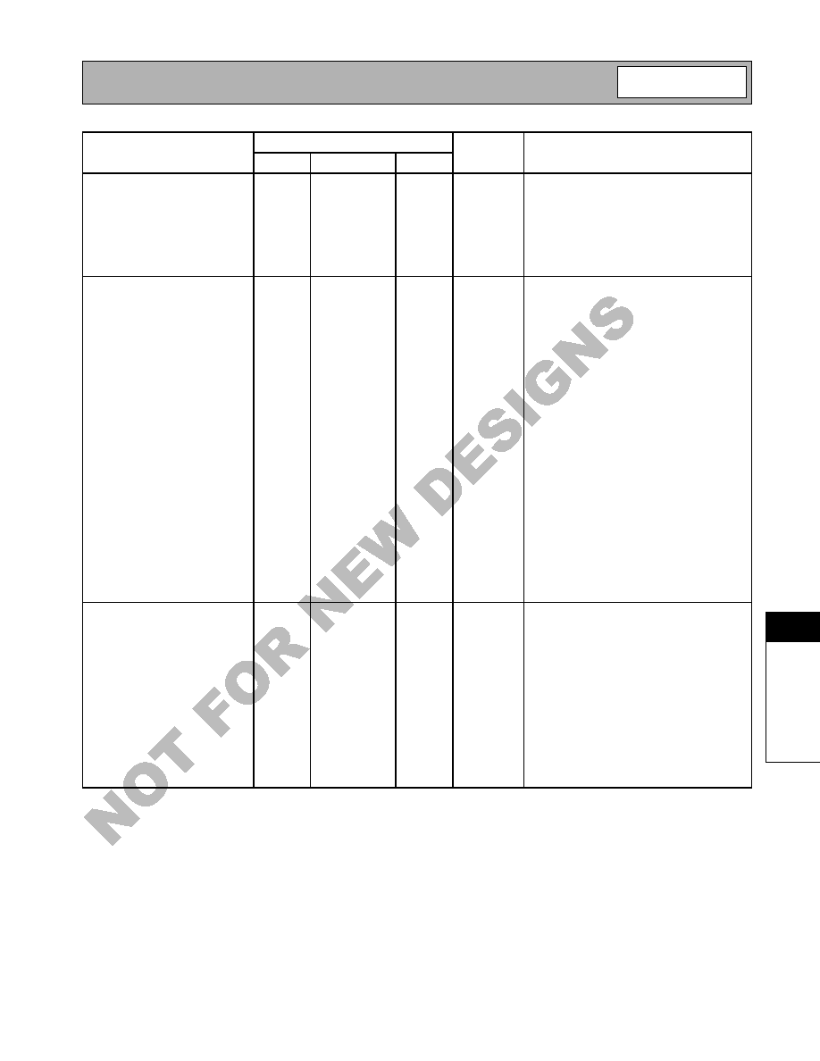
The RF2938 is a monolithic integrated circuit specifically
designed for direct-sequence spread-spectrum systems
operating in the 2.4GHz ISM band. The part includes a
direct conversion from IF receiver, quadrature demodula-
tor, I/Q baseband amplifiers with gain control and RSSI,
on-chip programmable baseband filters, dual data com-
parators. For the transmit side, a QPSK modulator and
upconverter
are provided. The design reuses the IF
SAW filter for transmit and receive reducing the number
of SAW filters required. Two cell or regulated three cell
(3.6V maximum) battery applications are supported by
the part. The part is also designed to be part of a 2.4GHz
chip set consisting of the RF2444 LNA/Mixer and one of
the many RFMD high efficiency GaAs HBT PA's and a
dual frequency synthesizer.
∑ 45MHz to 500MHz IF Quad Demod
∑ On-Chip Variable Baseband Filters
∑ Quadrature Modulator and Upconverter
∑ 2.7V to 3.6V Operation
∑ Part of 2.4GHz Radio Chipset
∑ 2.4GHz PA Driver
RF2938TR13
2.4GHz Spread-Spectrum Transceiver (Tape & Reel)
RF2938 PCBA
Fully Assembled Evaluation Board
2
Rev A9 020122
Dimensions in mm
9.00
+ 0.10
9.00
+ 0.20
0.22
+ 0.05
7∞ MAX
0∞ MIN
0.17 MAX.
0.60
0.15
0.10
+
0.10
0.00
1.00
+ 0.10
-A-
0.50
7.00
+ 0.10 sq.
4.57
+ 0.10 sq.
NOTES:
1. Shaded lead is Pin 1.
2. Lead coplanarity - 0.08 with respect to datum "A".
3. Leadframe material: EFTEC 64T copper or equivalent, 0.127 mm (0.005) thick.
4. Solder plating (85/15) on exposed area.
Exposed pad protrusion
0.0000 to 0.0127 (see note 4).
Package Style: TQFP-48 EDF, 9x9
See
Upg
ra
ded
P
rod
uct
RF2
94
8B

2-2
RF2938
Rev A9 020122
11
T
R
A
N
S
C
EI
VE
R
S
See
Upg
ra
ded
P
rod
uct
RF2
94
8B
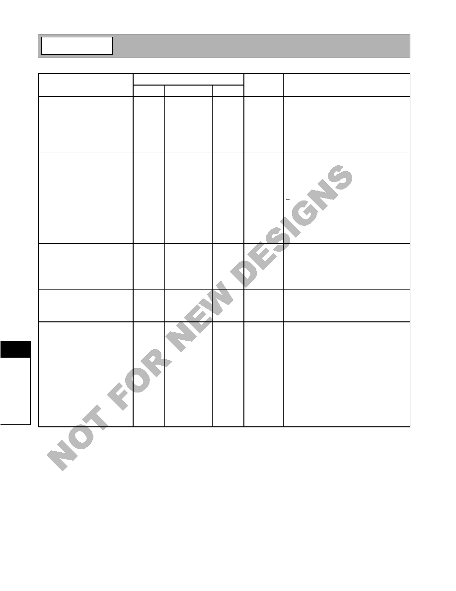
Absolute Maximum Ratings
Parameter
Rating
Unit
Supply Voltage
-0.5 to +3.6
V
DC
Control Voltages
-0.5 to +3.6
V
DC
Input RF Level
+12
dBm
LO Input Levels
+5
dBm
Operating Ambient Temperature
-40 to +85
∞C
Storage Temperature
-40 to +150
∞C
Moisture Sensitivity
JEDEC Level 5 @ 220∞C
Parameter
Specification
Unit
Condition
Min.
Typ.
Max.
Overall Receiver
T=25 ∞C, V
CC
= 3.3V, Freq= 280MHz,
R
BW
=10k
RX Frequency Range
45
500
MHz
Cascaded Voltage Gain
8 to 93
dB
Dependent upon RX VGC
Cascaded Noise Figure
5
dB
At maximum gain.
Cascaded Input IP
3
30
dB
µ
V
V
GC
< 1.2V
Cascaded Input IP
3
105
dB
µ
V
V
GC
>2.0V
RSSI Dynamic Range
60
dB
At V
GC
= 1.4V
RSSI Output Voltage Compli-
ance
1.1 to 2.3
V
Maximum RSSI is 2.5V or V
CC
-0.3, which-
ever is less. V
GC
= 1.4V
IF LO Leakage
-68
dBm
f= 280MHz, LO Power =-10dBm
Quadrature Phase Variation
±2
±5
∞
With expected LO amplitude and harmonic
content. R1= 270k
.
Quadrature Amplitude Offset
+0.25
dB
Q> I
Quadrature Amplitude Variation
±0.25
+0.5
dB
IF AMP and Quad Demod
Gain Control Range
43
dB
VGC < 1.2V max gain, VGC>2.0V=min gain
Noise Figure
5
dB
Single Sideband
IF Input Impedance
230- j400
Single ended. 280MHz
75- j350
Single ended. 374MHz
Input IP
3
-68
dBm
V
GC
< 1.2V
-8
dBm
V
GC
>2.0V
RX Baseband Amplifiers
THD
3
%
At maximum gain setting
3
%
At minimum gain setting
Gain Control Range
30
dB
V
GC
< 1.2V= max gain,
V
GC
> 2.0V= min gain
Output Voltage
500
mV
PP
R
L
>5k
, C
L
<5pF
DC Output Voltage
1.7
V
RX Baseband Filters
Baseband Filter 3dB Bandwidth
1
35
MHz
5th order Bessel LPF. Set by BW CTRL
Passband Ripple
0.1
dB
Baseband Filter 3dB Frequency
Accuracy
±10
±30
%
Group Delay
15
ns
At 35MHz, increasing as bandwidth
decreases.
Group Delay
400
ns
At 2MHz.
Baseband Filter Ultimate Rejec-
tion
> 80
dB
Output Impedance
20
Designed to drive> 5k
, <5pF load.
Caution! ESD sensitive device.
RF Micro Devices believes the furnished information is correct and accurate
at the time of this printing. However, RF Micro Devices reserves the right to
make changes to its products without notice. RF Micro Devices does not
assume responsibility for the use of the described product(s).
Refer to "Handling of PSOP and PSSOP Products" on page 16-15 for
special handling information.
Refer to "Soldering Specifications" on page 16-13 for special solder-
ing information.
2-3
RF2938
Rev A9 020122
11
T
R
A
N
S
C
EI
VE
R
S
See
Upg
ra
ded
P
rod
uct
RF2
94
8B
Parameter
Specification
Unit
Condition
Min.
Typ.
Max.
Data Amplifiers
Bandwidth
40
MHz
Gain (Limiting mode)
60
dB
Open Loop.
Rise and Fall Time
2
5
ns
5pF load.
Logic High Output
V
CC
- 0.3V
V
CC
V
Source Current 1mA
Logic Low Output
0.3
V
Sink Current 1mA.
Hysteresis
30
mV
Transmit Modulator and
LPF
Filter Gain
0
dB
Any setting
Baseband Filter 3dB Bandwidth
1
35
MHz
5th order Bessel LPF, Set by BW CTRL
Passband Ripple
0.1
dB
Group Delay
15
ns
At 35MHz, increasing as bandwidth
decreases.
Group Delay
400
ns
At 2MHz.
Ultimate Rejection
> 80
dB
Input Impedance
3
k
Single ended
Input AC Voltage
200
mV
p-p
Linear, Single ended.
Input DC Offset Requirement
1.6
1.7
1.8
V
For correct operation.
IF Frequency Range
45
500
MHz
Output Impedance
2
k
Open Collector when TX on, hi-Z when off
I/Q Phase Balance
±2
±5
I/Q Gain Balance
0.5±0.25
1.0
dB
Conversion Voltage Gain
1.1
V/V
With Current Combination into 50
single-
ended load
Output P1dB
-6
dBm
With Current Combination into 50
single-
ended load
Carrier Output
-30
dBm
Without external offset adjustments.
280MHz
Harmonic Outputs
-30
dBc
Transmit VGA and
Upconverter
VGA Gain Range
17
dB
VGA Input Voltage Range
1.0 to 2.0
V
Positive Slope
VGA Gain Sensitivity
17
dB/V
VGA Input Impedance
230-j400
280MHz
75-j350
374MHz
RF Mixer Output Impedance
50
With matching elements.
VGA/Mixer Conversion Gain
+10 to +27
dB
With 50
match on the output.
VGA/Mixer Output Power
-9
dBm
1dB compression - Single Side Band,
TX GC= 1.0V
VGA/Mixer Output Power
-4
dBm
1dB compression - Single Side Band,
TX GC= 2.0V
2-4
RF2938
Rev A9 020122
11
T
R
A
N
S
C
EI
VE
R
S
See
Upg
ra
ded
P
rod
uct
RF2
94
8B
Parameter
Specification
Unit
Condition
Min.
Typ.
Max.
Transmit Power Amp
Linear Output Power
6
dBm
Gain
23
dB
Output P1dB
12
dBm
Output Impedance
50
Input IP3
0
dBm
Input Impedance
50
Power Down Control
Logical Controls "ON"
V
CC
-0.3V
V
CC
+0.3V
V
Voltage supplied to the input, not to exceed
3.6V
Logical Controls "OFF"
-0.3
0
0.3
V
Voltage supplied to the input.
Control Input Impedance
>1
M
RSSI Response Time
1.8
µ
s
<8pF on RSSI output.
RX V
GC
Response TIme
200
ns
Full step in gain, to 90% of final output level.
RX EN Response TIme
2
µ
s
I/Q output VALID
TX EN Response TIme
330
ns
To IF output VALID
V
PD
to RX Response TIme
1.33
ms
To I/Q output VALID
V
PD
to TX Response TIme
50
µ
s
To IF output VALID
IF LO Input
The IF LO is divided by 2 and split into
quadrature signals to drive the frequency
mixers.
Input Impedance
1050-j1200
f= 560MHz
Input Power Range
-15
-10
0
dBm
peak
Input Frequency
90
1000
MHz
(2x IF Frequency)
RF LO Input
Input Impedance
33-j110
f= 2.16GHz untuned.
Input Power Range
-15
0
dBm
Input Frequency
2000
2400
MHz
Power Supply
Voltage
2.7
3.3
3.6
V
Total Current Consumption
V
CC
= 3.3V, Baseband BW 1MHz to 40MHz
Sleep Mode Current
1
µ
A
PD= 0, RX EN= 1, TX EN =1
PA Driver Current
48
mA
RX Current
BW (MHz)
0-11
65
mA
12-20
70
mA
20-30
110
mA
TX Current
BW (MHz)
Excluding PA Driver
0-11
95
mA
12-20
105
mA
20-30
115
mA

2-5
RF2938
Rev A9 020122
11
T
R
A
N
S
C
EI
VE
R
S
See
Upg
ra
ded
P
rod
uct
RF2
94
8B
Pin
Function
Description
Interface Schematic
1
NC
No internal connection. May be grounded or connected on adjacent
signal or left floating. Connect to ground for best results.
2
NC
No internal connection. May be grounded or connected on adjacent
signal or left floating. Connect to ground for best results.
3
PD
This pin is used to power up or down the transmit and receive base-
band sections. A logic high powers up the quad demod mixers, TX and
RX GmC LPF's, baseband VGA amps, data amps, and IF LO buffer
amp/ phase splitter. A logic low powers down the entire IC for sleep
mode. Also, see State Decode Table.
4
RX EN
Enable pin for the receiver 15dB gain IF amp and the RX VGA amp.
Powers up all receiver functions when PD is high, turns off the receiver
IF circuits when low. Also, see State Decode Table.
See pin 3.
5
TX EN
This pin is used to enable the transmit upconverter, buffer amps, 15db
IF amp, quad mod mixers, TX LO buffer, TX VGA, and PA driver. TX EN
is active low, when TX EN <1V, the transmit circuit is active if PD is
high. A logic high (TX EN >2V) disables the transmit IF/RF circuitry and
quad mod. Also, see State Decode Table.
See pin 3.
6
VCC1
Power supply for RX VGA amplifier, IC logic and RX references.
7
RX IF IN
IF input for receiver section. Must have DC blocking cap. The capacitor
value should be appropriate for the IF frequency. External matching to
50
recommended. For half duplex operation, connect RX IF IN and
TX IF IN signals together after the DC blocking caps, then run a trans-
mission line from the output of the IF SAW. AC coupling capacitor must
be less than 150pF to prevent delay in switching RX to TX/TX to RX.
See pin 8.
8
TX IF IN
Input for the TX IF signal after SAW filter. External DC blocking cap
required. External matching to 50
recommended. For half duplex
operation, connect RX IF IN and TX IF IN signals together after the DC
blocking caps, then run a transmission line from the output of the IF
SAW. AC coupling capacitor must be less than 150pF to prevent delay
in switching RX to TX/TX to RX.
9
VCC9
Power supply for the TX 15dB gain amp and TX VGA.
10
TX VGC
Gain control setting for the transmit VGA. Positive slope.
11
IF LO
IF LO input. Must have DC blocking cap. The capacitor value should be
appropriate for the IF frequency. LO frequency= 2xIF. Quad mod/
demod phase accuracy requires low harmonic content from IF LO, so it
is recommended to use an n= 3 LPF between the IF VCO and IF LO.
This is a high impedance input and the recommended matching
approach is to simply add a 100
shunt resistor at this input to con-
strain the mismatch. This pin requires a 6.5
µ
A DC bias current. This
can be accomplished with a 270k
resistor to V
CC
for 3.3V operation.
12
VCC8
Power supply for IF LO buffer and quadrature phase network.
13
NC
No internal connection. May be grounded or connected on adjacent
signal or left floating. Connect to ground for best results.
14
RF OUT
This is the output transistor of the power amp stage. It is an open col-
lector output. The output match is formed by an inductor to V
CC
, which
supplies DC and a series cap.
15
RF OUT
This is the output transistor of the power amp stage. It is an open col-
lector output. The output match is formed by an inductor to V
CC
, which
supplies DC and a series cap.
See pin 14.
16
VCC6
Power supply for the PA driver amp. This inductance to ground via
decoupling, along with an internal series capacitor, forms the interstage
match.
See pin 14.
10k
ESD
VCC
To Logic
Pins
3, 4, 5
D C B lo ck
50
µ
strip
IF
S A W
F ilte r
P in 7
Pin 8
IF V C O
C 2
1 5 0 p F
IF L O
P in 1 1
R e c o m m e n d e d M a tc h in g
N e tw o rk fo r IF L O
1 0 0
2 7 0 k
V
C C
From
TX RF
Image Filter
Bias
VCC6
Pin 16
V
CC
C
BYP
22 nF
V
CC
C
BYP
22 nF
PA OUT
Pin 14
PA OUT
Pin 15
PA IN
Pin 18
Power
Amp
Output
34 mA
14 mA
µ
st
ri
p
Bias