RF Monolithics, Inc.
Phone: (972) 233-2903
Fax: (972) 387-9148
E-mail: info@rfm.com
Page 1 of 2
RFM Europe
Phone: 44 1963 251383
Fax: 44 1963 251510
http://www.rfm.com
©1999 by RF Monolithics, Inc. The stylized RFM logo are registered trademarks of RF Monolithics, Inc.
RO2164A_RO2164A-1_RO2164A-2_071101
Electrical Characteristics
Characteristic
Sym
Notes
Minimum
Typical
Maximum
Units
Frequency (+25 ∞C) Nominal Frequency RO2164A
f
C
2,3,4,5
868.275
868.425
MHz
RO2164A-1
868.200
868.500
RO2164A-2
868.250
868.450
Tolerance from 868.35 MHz RO2164A
f
C
±75
kHz
RO2164A-1
±150
RO2164A-2
±100
Insertion Loss
IL
2,5,6
1.1
2.0
dB
Quality Factor
Unloaded Q
Q
U
5,6,7
24,737
50
Loaded Q
Q
L
4,000
Temperature Stability
Turnover Temperature
T
O
6,7,8
10
25
40
∞C
Turnover Frequency
f
O
f
C
kHz
Frequency Temperature Coefficient
FTC
0.032
ppm/∞C
2
Frequency Aging
Absolute Value during the First Year
|fA|
1
<±10
ppm/yr
DC Insulation Resistance between Any Two Terminals
5
1.0
M
RF Equivalent RLC Model
Motional Resistance
R
M
5, 6, 7, 9
19.2889
Motional Inductance
L
M
87.455
µH
Motional Capacitance
C
M
0.3841
fF
Shunt Static Capacitance
C
O
5, 6, 9
3.1
pF
Test Fixture Shunt Inductance
L
TEST
2, 7
10.8365
nH
Lid Symbolization (in addition to Lot and/or Date Codes)
260
∑
Ideal for European 868.35 MHz Transmitters
∑
Very Low Series Resistance
∑
Quartz Stability
∑
Surface-Mount Ceramic Case with 21 mm
2
Footprint
The RO2164A is a true one-port, surface-acoustic-wave (SAW) resonator in a surface-mount ceramic case.
It provides reliable, fundamental-mode, quartz frequency stabilization of fixed-frequency transmitters operat-
ing at 868.35 MHz. This SAW is designed specifically for remote-control and wireless security transmitters
operating under ETSI-ETS 300 220 in Europe and under FTZ 17 TR 2100 in Germany.
Absolute Maximum Ratings
Rating
Value
Units
CW RF Power Dissipation
+5
dBm
DC Voltage Between Terminals
±30
VDC
Case Temperature
-40 to +85
∞C
Soldering Temperature
+250
∞C
868.35 MHz
SAW
Resonator
RO2164A
RO2164A-1
RO2164A-2
CAUTION: Electrostatic Sensitive Device. Observe precautions for handling.
Notes:
1.
Frequency aging is the change in f
C
with time and is specified at +65∞C or less.
Aging may exceed the specification for prolonged temperatures above +65∞C.
Typically, aging is greatest the first year after manufacture, decreasing in subse-
quent years.
2.
The center frequency, f
C
, is measured at the minimum insertion loss point,
IL
MIN
, with the resonator in the 50
test system (VSWR
1.2:1). The shunt
inductance, L
TEST
, is tuned for parallel resonance with C
O
at f
C
. Typically, f
OS-
CILLATOR
or f
TRANSMITTER
is approximately equal to the resonator f
C
.
3.
One or more of the following United States patents apply: 4,454,488 and
4,616,197.
4.
Typically, equipment utilizing this device requires emissions testing and govern-
ment approval, which is the responsibility of the equipment manufacturer.
5.
Unless noted otherwise, case temperature T
C
= +25∞C±2∞C.
6.
The design, manufacturing process, and specifications of this device are subject
to change without notice.
7.
Derived mathematically from one or more of the following directly measured
parameters: f
C
, IL, 3 dB bandwidth, f
C
versus T
C
, and C
O
.
8.
Turnover temperature, T
O
, is the temperature of maximum (or turnover) fre-
quency, f
O
. The nominal frequency at any case temperature, T
C
, may be calcu-
lated from: f = f
O
[1 - FTC (T
O
-T
C
)
2
]. Typically
oscillator T
O
is approximately
equal to the specified
resonator T
O
.
9.
This equivalent RLC model approximates resonator performance near the reso-
nant frequency and is provided for reference only. The capacitance C
O
is the
static (nonmotional) capacitance between the two terminals measured at low
frequency (10 MHz) with a capacitance meter. The measurement includes para-
sitic capacitance with "NC" pads unconnected. Case parasitic capacitance is
approximately 0.05 pF. Transducer parallel capacitance can by calculated as:
C
P
C
O
- 0.05 pF.
SM-2 Case
868.35 MHz SAW Resonator
RF Monolithics, Inc.
Phone: (972) 233-2903
Fax: (972) 387-9148
E-mail: info@rfm.com
Page 2 of 2
RFM Europe
Phone: 44 1963 251383
Fax: 44 1963 251510
http://www.rfm.com
©1999 by RF Monolithics, Inc. The stylized RFM logo are registered trademarks of RF Monolithics, Inc.
RO2164A_RO2164A-1_RO2164A-2_071101
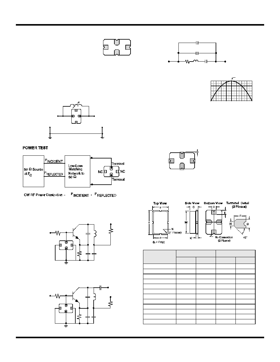
Electrical Connections
The SAW resonator is bidirectional and may be in-
stalled with either orientation. The two terminals
are interchangeable and unnumbered. The callout
NC indicates no internal connection. The NC pads
assist with mechanical positioning and stability.
External grounding of the NC pads is recommend-
ed to help reduce parasitic capacitance in the cir-
cuit.
Typical Test Circuit
The test circuit inductor, L
TEST
, is tuned to resonate with the static capaci-
tance, C
O
, at F
C
.
Typical Application Circuits
Equivalent LC Mode
l
Temperature Characteristics
The curve shown on the right
accounts for resonator contri-
bution only and does not in-
clude LC component tempera-
ture contributions
.
Typical Circuit Board
Land Pattern
The circuit board land pattern shown below is one possible design. The op-
timum land pattern is dependent on the circuit board assembly process
which varies by manufacturer. The distance between adjacent land edges
should be at a maximum to minimize parasitic capacitance. Trace lengths
from terminal lands to other components should be short and wide to mini-
mize parasitic series inductances.
Case Design
The case material is black alumina with contrasting symbolization. All pads
are nominally centered with respect to the base and consist of 60 to 100 mi-
croinches (min) electroless gold on 50 micorinches (min) electroless nickel.
NC
NC
Terminal
Terminal
From 50
Network Analyzer
Network Analyzer
To 50
ELECTRICAL TEST
+9VDC
47
RF Bypass
L1
(Antenna)
C1
C2
200k
Modulation
Input
ROXXXXA
Bottom View
470
Typical Low-Power Transmitter Application
RF Bypass
L1
C1
C2
ROXXXXA
Bottom View
Typical Local Oscillator Application
+VDC
+VDC
Output
Dimensions
Millimeters
Inches
Min
Max
Min
Max
A
5.97
0.235
B
3.94
0.155
C
2.16
0.085
D
0.94
1.10
0.037
0.043
E
0.83
1.20
0.033
0.047
F
1.16
1.53
0.046
0.060
G
0.94
1.10
0.037
0.043
H
0.43
0.59
0.017
0.023
K
0.43
0.59
0.017
0.023
M
5.31
0.209
N
0.38
0.64
0.015
0.025
P
3.28
0.129
0.05 pF*
0.05 pF
Cp
Co
+
=
*Case Parasitics
Cp
Rm
Lm
Cm
-80 -60 -40 -20
0 +20 +40 +60
0
-50
-100
-150
+80
-200
0
-50
-100
-150
-200
f
C
= f
O
, T
C
= T
O
T =
T
C
- T
O
( ∞C )
(f-
f o
o
) /
f
(ppm
)
Typical Dimension:
0.010 to 0.047 inch
(0.25 to 1.20 mm)
(4 Places)