Rhopoint Components Ltd
Fax: +44 (0) 1883 712938 Phone: +44 (0) 1883 717988 web: www.rhopointcomponents.com e-mail: sales@rhopointcomponents.com
RI-60 Series
RI-60 S
RI-60 S
RI-60 S
RI-60 S
RI-60 S
ERIES
ERIES
ERIES
ERIES
ERIES
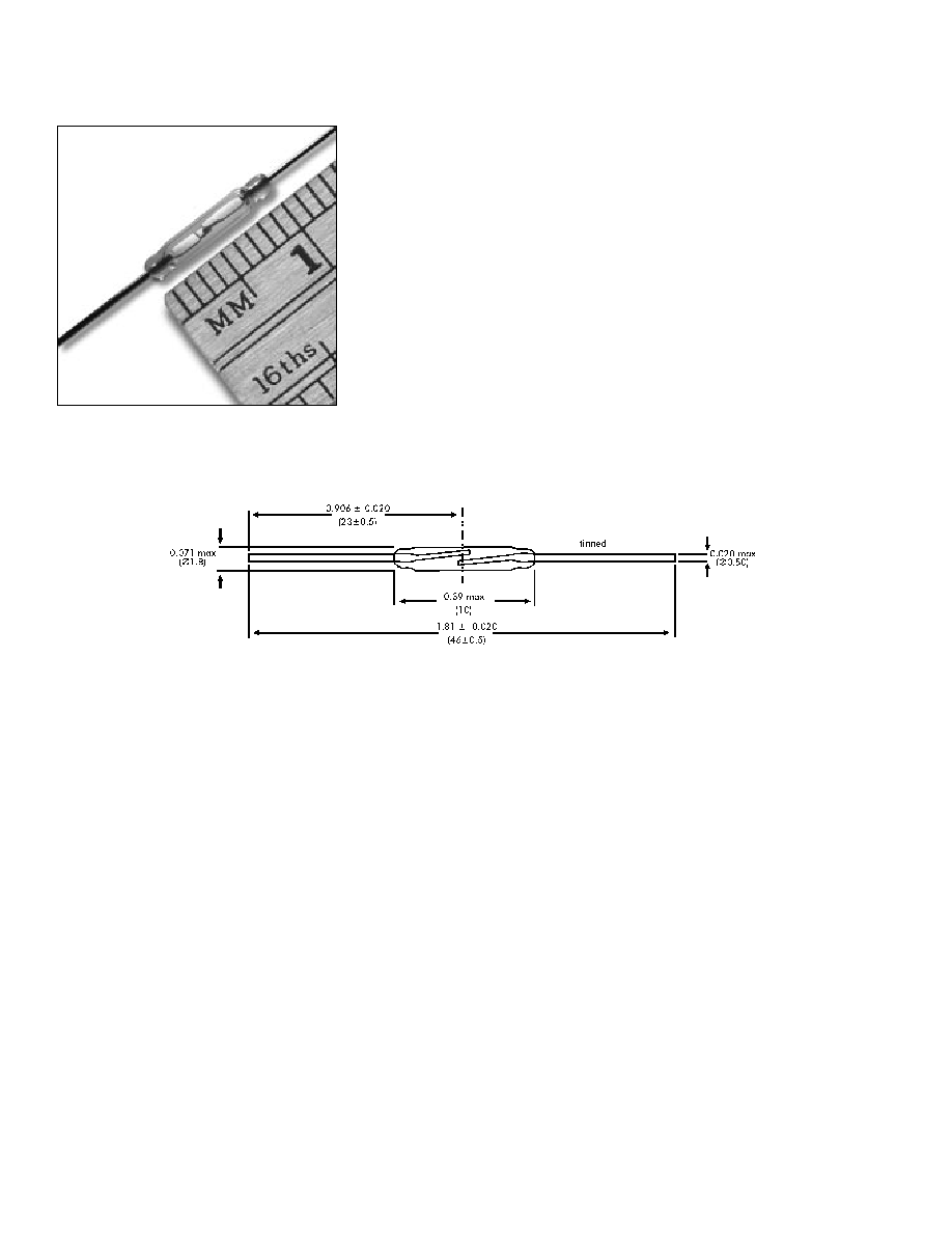
Ultra-miniature dry-reed switch hermetically sealed in a gas-filled
glass envelope. Single-pole, single-throw (SPST) type, having
normally open contacts, and containing two magnetically actuated
reeds.
The switch is of the double-ended type and may be actuated by an
electromagnet, a permanent magnet or a combination of both.
The device is intended for use in relays, sensors, pulse counters or
similar devices.
RI-60 S
RI-60 S
RI-60 S
RI-60 S
RI-60 S
ERIES
ERIES
ERIES
ERIES
ERIES
F
F
F
F
F
EA
EA
EA
EA
EATURES
TURES
TURES
TURES
TURES
u
Ideal for ATE switching
u
Contact layers: Gold, sputtered ruthenium
u
Superior glass-to-metal seal and blade alignment
u
Excellent life expectancy and reliability
G
G
G
G
G
ENERAL
ENERAL
ENERAL
ENERAL
ENERAL
D
D
D
D
DA
A
A
A
AT
T
T
T
TA
A
A
A
A
FOR
FOR
FOR
FOR
FOR
ALL
ALL
ALL
ALL
ALL
MODELS
MODELS
MODELS
MODELS
MODELS
RI-60
RI-60
RI-60
RI-60
RI-60
A
A
A
A
AT
T
T
T
T-Customiza
-Customiza
-Customiza
-Customiza
-Customization / Pr
tion / Pr
tion / Pr
tion / Pr
tion / Pref
ef
ef
ef
efor
or
or
or
ormed Leads
med Leads
med Leads
med Leads
med Leads
Besides the standard models, customized products can
also be supplied offering the following options:
! Operate and release ranges to customer specification
! Cropped and/or preformed leads
C
C
C
C
C
OILS
OILS
OILS
OILS
OILS
All characteristics are measured using the Philips stan-
dard coil. For definitions of the Philips Standard Coil and
the standard MIL Coil, refer to "Application Notes" in
the Reed Switch Technical & Application Information
Section of this catalog.
Rela
Rela
Rela
Rela
Relationship betw
tionship betw
tionship betw
tionship betw
tionship between Philips Standar
een Philips Standar
een Philips Standar
een Philips Standar
een Philips Standard Coil and the
d Coil and the
d Coil and the
d Coil and the
d Coil and the
Standar
Standar
Standar
Standar
Standard MIL Coil
d MIL Coil
d MIL Coil
d MIL Coil
d MIL Coil
Operate value of standard MIL Coil = 0.83 x operate
value of Philips Sandard Coil + 0.30 AT.
Release value of standard MIL Coil = 0.83 x release
value of Philips Standard Coil + 0.18 AT.
L
L
L
L
L
IFE
IFE
IFE
IFE
IFE
EXPECT
EXPECT
EXPECT
EXPECT
EXPECTANCY
ANCY
ANCY
ANCY
ANCY
AND
AND
AND
AND
AND
RELIABILITY
RELIABILITY
RELIABILITY
RELIABILITY
RELIABILITY
The life expectancy data given below are valid for a coil
energized at 1.25 times the published maximum operate
value for each type in the RI-60 series.
No-load conditions (oper
No-load conditions (oper
No-load conditions (oper
No-load conditions (oper
No-load conditions (opera
aa
a
ating fr
ting fr
ting fr
ting fr
ting frequenc
equenc
equenc
equenc
equency:
y:
y:
y:
y: 100 Hz)
100 Hz)
100 Hz)
100 Hz)
100 Hz)
Life expectancy: min.10
9
operations with a failure rate of
less than 2 x10
-10
with a confidence level of 90%.
End of life criteria:
Contact resistance > 1
after 2 ms
Release time > 2ms (latching or contact sticking).
Loaded conditions (r
Loaded conditions (r
Loaded conditions (r
Loaded conditions (r
Loaded conditions (resisti
esisti
esisti
esisti
esistiv
v
v
v
ve load:
e load:
e load:
e load:
e load: 5
5
5
5
5 V
V
V
V
V; 100 mA;
; 100 mA;
; 100 mA;
; 100 mA;
; 100 mA;
oper
oper
oper
oper
opera
aa
a
ating fr
ting fr
ting fr
ting fr
ting frequenc
equenc
equenc
equenc
equency:
y:
y:
y:
y: 125 Hz)
125 Hz)
125 Hz)
125 Hz)
125 Hz)
Life expectancy: min. 2 x 10
7
operations with a failure
rate of less than 10
-8
with a confidence level of 90%.
End of life criteria:
Contact resistance > 1
after 2.5 ms
Release time > 1 ms (latching or contact sticking).
Loaded conditions (r
Loaded conditions (r
Loaded conditions (r
Loaded conditions (r
Loaded conditions (resisti
esisti
esisti
esisti
esistiv
v
v
v
ve load:
e load:
e load:
e load:
e load: 20
20
20
20
20 V
V
V
V
V; 500 mA;
; 500 mA;
; 500 mA;
; 500 mA;
; 500 mA;
oper
oper
oper
oper
opera
aa
a
ating fr
ting fr
ting fr
ting fr
ting frequenc
equenc
equenc
equenc
equency:
y:
y:
y:
y: 125 Hz)
125 Hz)
125 Hz)
125 Hz)
125 Hz)
Life expectancy: min. 2 x 10
7
operations with a failure
rate of < 10
-8
with a confidence level of 90%.
Dimensions in inches (mm)
Rhopoint Components Ltd
Fax: +44 (0) 1883 712938 Phone: +44 (0) 1883 717988 web: www.rhopointcomponents.com e-mail: sales@rhopointcomponents.com
End of life criteria:
Contact resistance > 2
after 2.5 ms
Release time > 2.5 ms (latching or contact sticking).
Switching different loads involves different life expect-
ancy and reliability data. Further information is available
on request.
M
M
M
M
M
ECHANICAL
ECHANICAL
ECHANICAL
ECHANICAL
ECHANICAL
D
D
D
D
D
A
A
A
A
AT
T
T
T
TA
A
A
A
A
Contact arrangement is normally open; lead finish is
tinned; net mass is approximately 0.09 g; and can be
mounted in any position.
S
S
S
S
S
HOCK
HOCK
HOCK
HOCK
HOCK
The switches are tested in accordance with "IEC 68-2-
27", test Ea (peak acceleration 100 G, half sinewave;
duration 11 ms). Such a shock will not cause an open
switch (no magnetic field present) to close.
M
M
M
M
M
ECHANICAL
ECHANICAL
ECHANICAL
ECHANICAL
ECHANICAL
S
S
S
S
S
TRENGTH
TRENGTH
TRENGTH
TRENGTH
TRENGTH
The robustness of the terminations is tested in accordance
with "IEC 68-2-21", test Ua
1
(load 10 N).
O
O
O
O
O
PERA
PERA
PERA
PERA
PERATING
TING
TING
TING
TING
AND
AND
AND
AND
AND
S
S
S
S
S
T
T
T
T
TORA
ORA
ORA
ORA
ORAGE
GE
GE
GE
GE
T
T
T
T
T
EMPERA
EMPERA
EMPERA
EMPERA
EMPERATURE
TURE
TURE
TURE
TURE
Operating ambient temperature; min: -55
∞
C;
max: +125
∞
C.
Storage temperature; min: -55
∞
C; max: +125
∞
C.
Note:
Note:
Note:
Note:
Note: Temperature excursions up to 150
∞
C may be
permissible. For more information contact your nearest
Coto Technology sales office.
S
S
S
S
S
OLDERING
OLDERING
OLDERING
OLDERING
OLDERING
The switch can withstand soldering heat in accordance
with "IEC 68-2-20", test Tb, method 1B: solder bath at
350 ±10∞ C for 3.5 ±0.5 s.
Solderability is tested in accordance with "IEC 68-2-20"
test Ta, method 3: solder globule temperature 235
∞
C;
ageing 1b: 4 hours steam.
W
W
W
W
W
ELDING
ELDING
ELDING
ELDING
ELDING
The leads can be welded.
M
M
M
M
M
OUNTING
OUNTING
OUNTING
OUNTING
OUNTING
The leads should not be bent closer than 1 mm to the
glass-to-metal seals. Stress on the seals should be
avoided. Care must be taken to prevent stray magnetic
fields from influencing the operating and measuring
conditions.
RI-60 Series
Model Number
RI-60
Parameters
Test Conditions
Units
Operating Characteristics
Operate Range
AT
9-21
Release Range
AT
5-16
Operate Time - including bounce (typ.)
(energization)
ms
0.15 (25 AT)
Bounce Time (typ.)
(energization)
ms
0.035 (25 AT)
Release Time (max)
(energization)
µs
20 (25 AT)
Resonant Frequency (typ.)
Hz
11300
Electrical Characteristics
Switched Power (max)
W
10
Switched Voltage DC (max)
V
200
Switched Voltage AC, RMS value (max)
V
140
Switched Current DC (max)
mA
500
Switched Current AC, RMS value (max)
mA
500
Carry Current DC; AC, RMS value (max)
mA
500
Breakdown Voltage (min)
V
230
Contact Resistance (initial max)
(energization)
m
115 (25 AT)
Contact Resistance (initial typ.)
(energization)
m
95 (25 AT)
Contact Capacitance (max)
without test coil
pF
0.25
Insulation Resistance (min)
RH
45%
M
10
6