689
Motor driver ICs
2-phase half-wave motor predriver
BA6402F
The BA6402F is a 2-phase, half-wave motor predriver suitable for fan motors.
F
Features
1) Lock detection and rotational speed sensing mecha-
nisms are built in.
2) Hall constant current source is built in.
3) Compact 8-pin SOP package reduces the number of
external components required.
F
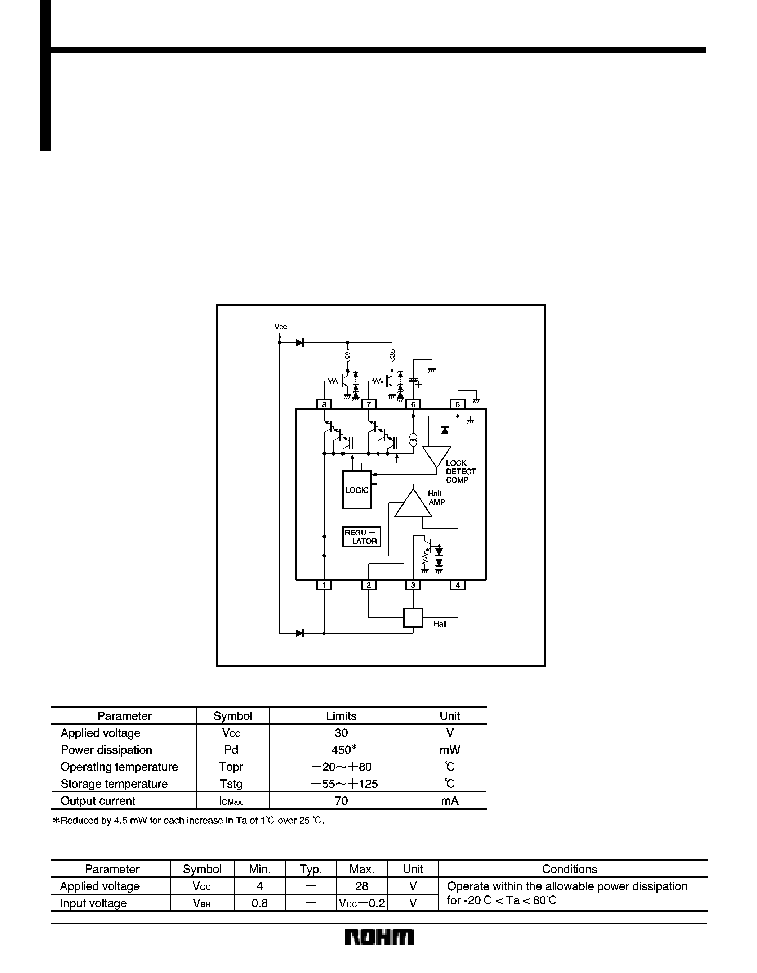
Block diagram and application example
F
Absolute maximum ratings (Ta = 25
_
C)
F
Recommended operating conditions
690
Motor driver ICs
BA6402F
F
Electrical characteristics (unless otherwise noted, Ta = 25
_
C and V
CC
= 12V)
F
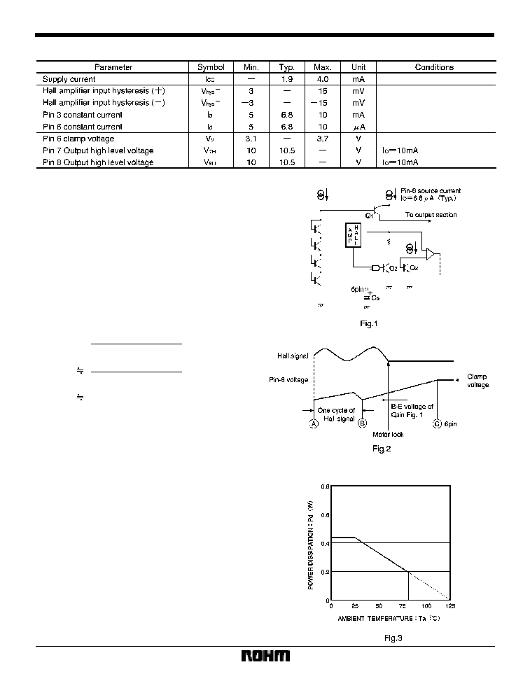
Rotational speed sensing and lock detection (6 pin)
The circuit around pin 6 is described in Fig. 1. Normally,
the C
6
external capacitor is charging or discharging
around the Hall signal when the motor is running. When
the motor is locked, discharging does not occur at C
6
be-
cause the Hall signal stops switching. Charging contin-
ues at C
6
until the voltage increases to the pin-6 clamp
voltage, and then Q
1
turns ON to turn OFF the output.
With the pin-6 current being constant (I
6
=6.8
�
A, typical),
the time required after the motor is locked until the output
current is turned OFF (duration between B and C in Fig.
2) is determined by the C
6
capacitance.
where V
6CL
is pin-6 clamp voltage (nearly equal to 5V
BE
)
For C
6
=2.2
�
F, for example, T
off
is about 0.91s (typical).
F
Operation notes
(1)
Hall constant current source (3 pin, 6.8mA typical-
ly), which is directly connected with the IC bias circuit, is
not available when pin 3 is OPEN (saturated).
(2)
Power dissipation
The allowable power dissipation is plotted against ambi-
ent temperature in Fig. 3.
F
Thermal derating curve
I
6
T
off
=T
B
X
C
=
(V
6CL
*
V
BEQ3
) C
6
4.12
10
5
C
6
(sec) (Typ.)
6.8
�
A (Typ.)
4V
BE
S
C
6
691
Motor driver ICs
BA6402F
(3)
Power dissipation
The power consumed in the IC can be calculated from
the following equation :
(
1) P
C1
is power consumed by the circuit current.
P
C1
=V
CC
I
CC
(
2) P
C2
is power consumed by the Hall current (pin 3).
P
C2
=I
3
V
3
where V
3
=pin 3 voltage. Connecting a resistor between
the V
CC
pin and pin 3 effectively reduces the IC current
consumption.
(
3) P
C3
is power consumed by the output current.
P
C3
=(V
CC
*
V
OH
)
I
O
V
OH
is the HIGH level voltage of pins 7 and 8. Power con-
sumption can be reduced by raising the h
FE
-rank of the
external output transistor and thereby reducing the I
O
val-
ue. Make sure that your application does not exceed the
allowable power dissipation of the IC.
(4) Restarting when motor is locked
The outputs are turned OFF if the motor is stopped for
some reason. To restart the motor from this situation, turn
off the power first, fully discharge the pin 6 capacitor next,
and then turn on the power again.
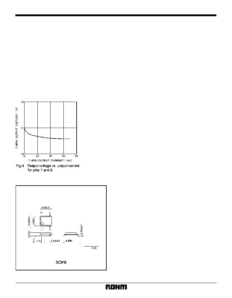
F
Electrical characteristic curve
F
External dimensions (Units: mm)
n=1
P
C
=
P
Cn
3