804
Audio ICs
Fluorescent display tube level meter
driver, 16-point
2 channel, VU scale,
bar display
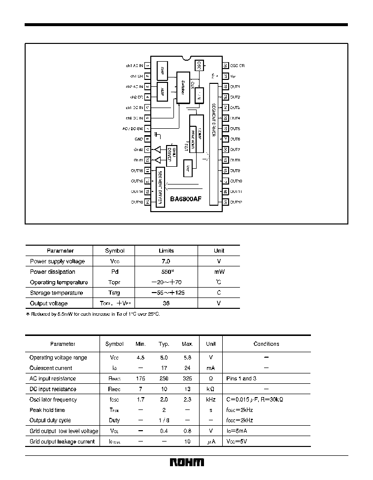
BA6800AF
The BA6800AF is a two-channel, 16-point fluorescent display tube driver for VU-scale bar-level meters.
It uses a dynamic-drive system and is provided with both AC and DC inputs. The AC input mode has a peak hold circuit.
The IC features a power-on mute, and the output block can directly drive fluorescent display tubes, so few external com-
ponents are required.
F
Applications
Level meters for all types of AV equipment
F
Features
1) Uses dynamic-drive system to display two 16-point
channels. 28-pin SOP package.
2) AC and DC inputs provided. Switching function al-
lows two-mode display.
3) Upper 12 points have peak hold function in AC mode
(two seconds).
4) Power-on mute function.
5) Dynamic-drive system reduces the power dissipa-
tion of the fluorescent display tube power supply.
6) Square root compression amplifier built in.
808
Audio ICs
BA6800AF
F
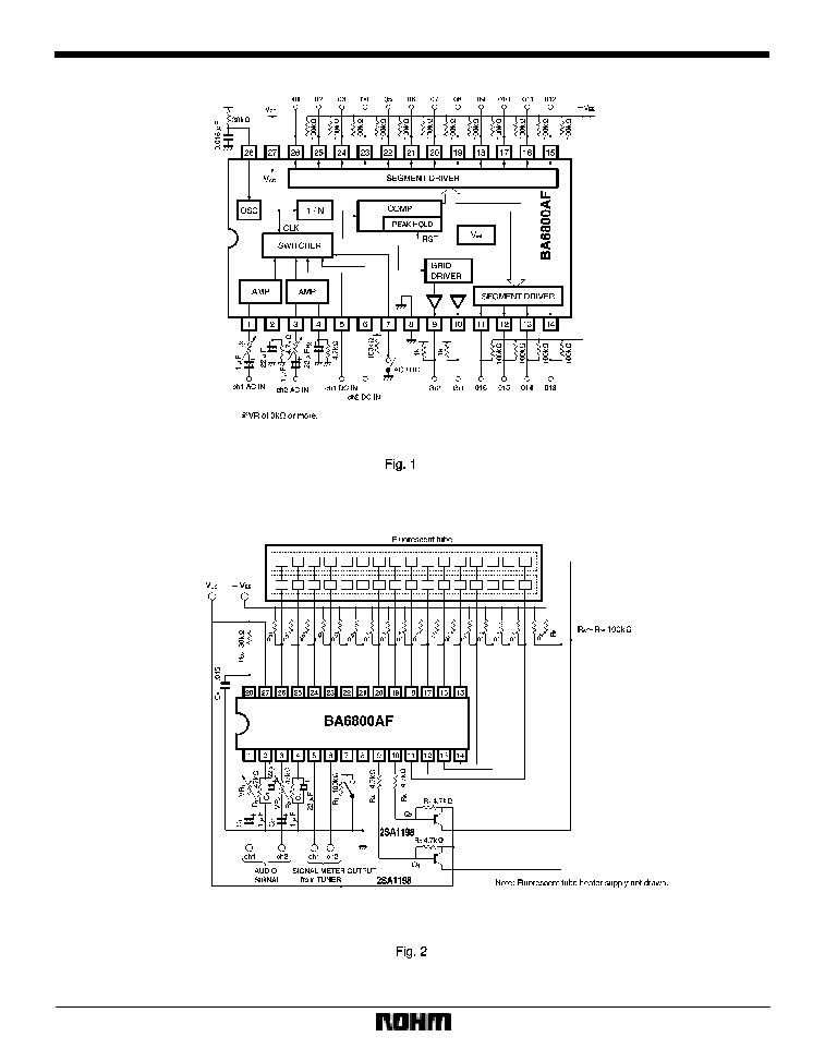
Circuit operation
(1)
Input block
The AC input pins are pins 1 and 3, and the DC input pins
are pins 5 and 6. Pin 7 is used to switch between the AC
and DC inputs. When the input to pin 7 is "H", AC input
is selected (pins 1 and 3). Therefore, by using pin 7 to
switch between the AC and DC modes, the IC can do two
jobs. For example, pins 1 and 3 can be used for audio sig-
nal input, and pins 5 and 6 can be used as the input for
the signal meter output from a tuner (DC).
The AC input impedance of pins 1 and 3 is a low 250
(Typ.), so connect potentiometers (VR
1
and VR
2
) in se-
ries with the inputs to adjust the sensitivity and ch1 and
ch2 balance.
(2)
Peak hold circuit
The BA6800AF have peak hold circuits that temporarily
holds peak signal levels in AC input mode.
The peak hold function can be used with the upper 12
points (5 to 16). The peak hold time depends on the oscil-
lator frequency. It is 2 sec. (Typ.) for an oscillator frequen-
cy of 2kHz.
DC mode does not have a peak hold function.
(3)
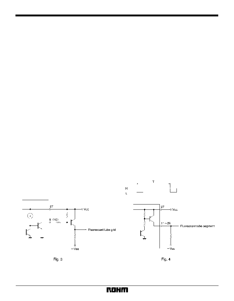
Grid output
The pin 9 and 10 grid outputs are open-collector NPN
transistors. The logic is active low (the fluorescent tube
lights when the output is "L"), so connect two PNP tran-
sistors Q
1
and Q
2
as shown in the application example
circuit to drive the fluorescent tubes (see Fig. 3).
(4)
Segment output block
Pins 11 to 26 are the segment outputs. The output circuits
are open-collector PNP transistors. When grid 1 is "L",
the ch1 level is output (pin 1 or 5 input level), and when
grid 2 is "L", the ch2 level is output (pin 3 or 6 input level).
Refer to Fig. 4.
(5)
Grid and segment output timing chart. The grid and
segment output timing for an oscillator frequency of 2kHz
is shown in Fig. 5.
(6)
Attack and release times
The response characteristic for AC input signals is set by
resistor R
1
and capacitor C
3
for ch1 and resistor R
2
and
capacitor C
4
for ch2 (pins 2 and 4). When R
1
= 47k
and
C
3
= 22
µ
F, the attack time is about 4ms, and the release
time is about 1sec. (same for ch2).
Attack time
: Time for the voltage on pins 2 and 4
to rise from 1V to 2.5V when the in-
put goes from no input to 2.6Vrms,
then back to no input.
Release time : Time for the voltage on pins 2 and 4
to fall from 2.5V to 1V when the input
goes from 2.6Vrms to no input.
(7)
Oscillator frequency
The resistor R
26
and capacitor C
5
connected to pin 28 de-
termine the oscillator frequency.
The oscillator frequency (f
osc
) and grid output period (T)
are related as follows :
T (ms) = 16 / f
osc
(kHz)