712
Motor driver ICs
Fan motor driver IC
BA6811F / BA6813F
The BA6811F and BA6813F are 2-phase, half-wave motor drivers suited for 12V fan motors. Built-in lock detection and
automatic restart mechanisms protect motors. Compact SOP8 (BA6811F / BA6813F) packages reduce the number of
external components required.
F
Applications
2-phase fan motors
F
Features
1) Built-in power transistors.
2) Lock detection and automatic restart mechanisms.
3) Built-in thermal shutdown circuit.
4) Alarm output pin. (BA6811F)
5) Hall signal output pin. (BA6813F)
6) Built-in reverse current protection diode.
F
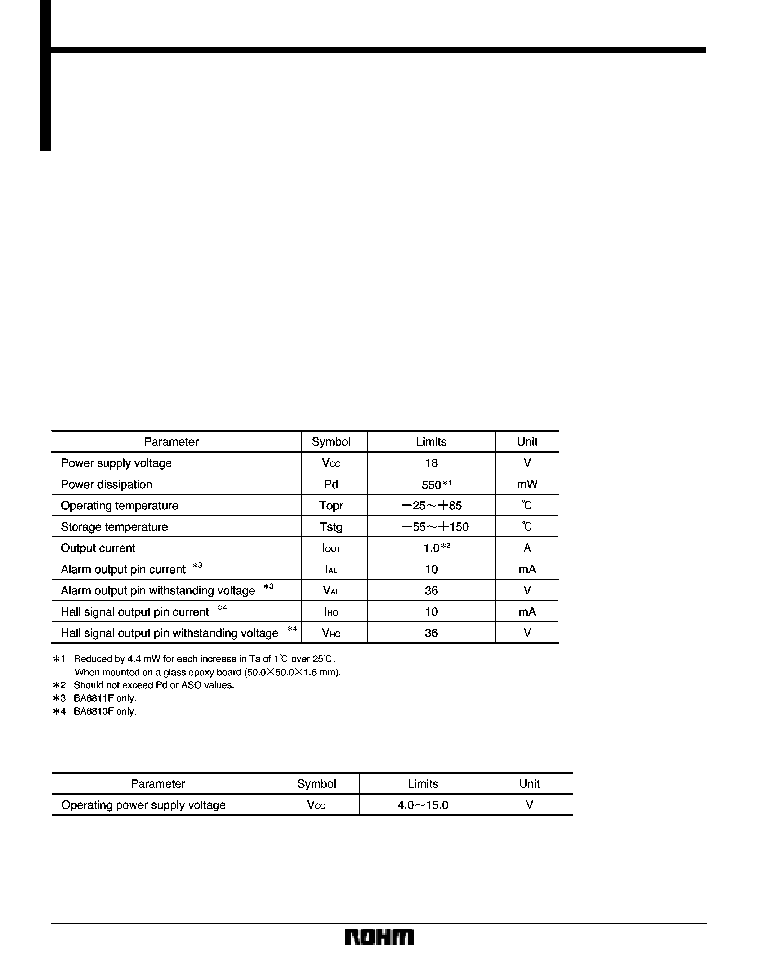
Absolute maximum ratings (Ta = 25
_
C)
F
Recommended operating conditions (Ta = 25
_
C)
714
Motor driver ICs
BA6811F / BA6813F
F
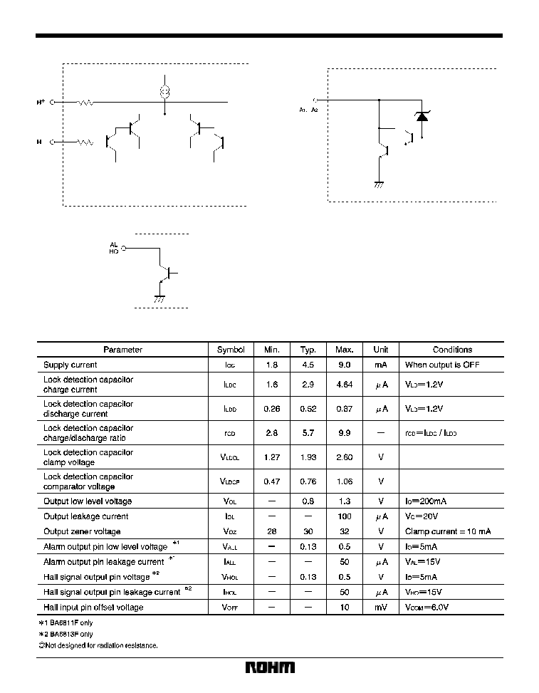
Input / output equivalent circuits
F
Electrical characteristics (unless otherwise noted, Ta = 25
_
C, V
CC
= 12V)
715
Motor driver ICs
BA6811F / BA6813F
F
Circuit operation
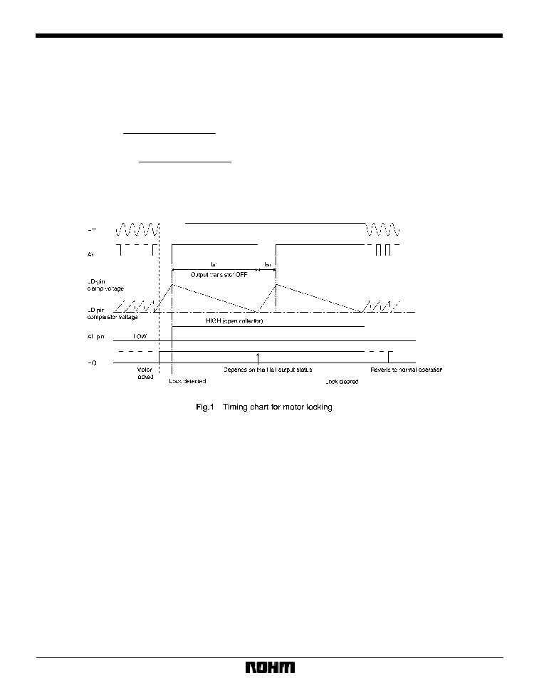
The BA6811F and BA6813F have motor lock detection
and automatic restart circuits. The timing of lock detec-
tion and automatic restart is determined by the external
capacitor connected to the LD pin. The charge time of the
external capacitor is given by :
(Typical value)
where
V
LDCL
is the LD-pin clamp voltage
(1.93V),
V
LDCP
is the LD-pin comparator voltage
(0.76V),
I
LDC
is the LD-pin charge current
(2.9
�
A),
I
LDD
is the LD-pin discharge current
(0.52
�
A),
C is the capacitance of the LD-pin external capacitor.
For C=1
�
F, for example, the charge (output ON) and dis-
charge (output OFF) times are 0.40s and 2.25s, respec-
tively.
The timing chart for an occasion of motor locking is
shown in Fig. 1.
I
LDC
T
ON
(Charge time)=
C
S
(V
LDCL
*
V
LDCP
)
I
LDD
T
OFF
(Discharge time)=
C
S
(V
LDCL
*
V
LDCP
)
716
Motor driver ICs
BA6811F / BA6813F
F
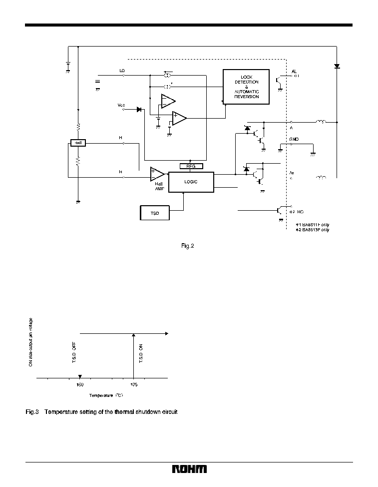
Application example
F
Operation notes
(1)
Thermal shutdown circuit
The IC has a built-in thermal shutdown circuit. The is a
temperature difference of 25
_
C (typical) between the
temperatures at which the circuit is activated and deacti-
vated.
The circuit is activated at the temperature of about 175
_
C
(typical), so that all outputs are turned OFF. Normal op-
eration resumes when the circuit is deactivated.
(2)
Power consumption
Power consumed in the IC can be calculated from the fol-
lowing equation :
P
C
=P
C
1
)
P
C
2
)
P
C
3
P
C
1 is power consumed by the circuit current.
P
C
1=V
CC
I
CC
P
C
2 is the output current consumption.
P
C
2=V
OL
I
O
V
OL
is the LOW level output voltage of output pins
1 and 2, and I
O
is the sink current of pins 1 and 2.
P
C
3 is power consumed by the AL and HO pins.
P
C3
=V
ALL
I
AL
)
V
HOL
I
HO
/ 2
where
V
ALL
is the AL-pin LOW level voltage,
I
AL
is the AL-pin sink current,
V
HOL
is the HO-pin LOW level voltage,
I
HO
is the HO-pin sink current.
Make sure that your application does not exceed the al-
lowable power dissipation of the IC.
