717
Motor driver ICs
Fan motor driver IC
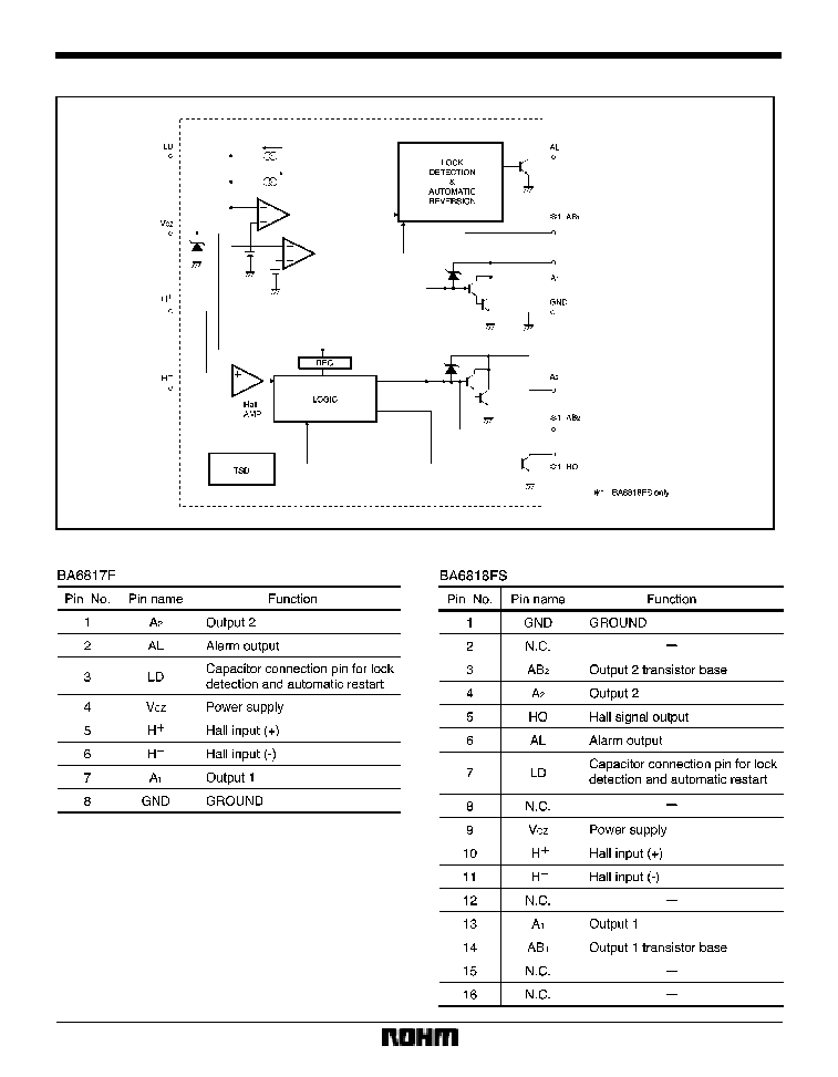
BA6817F / BA6818FS
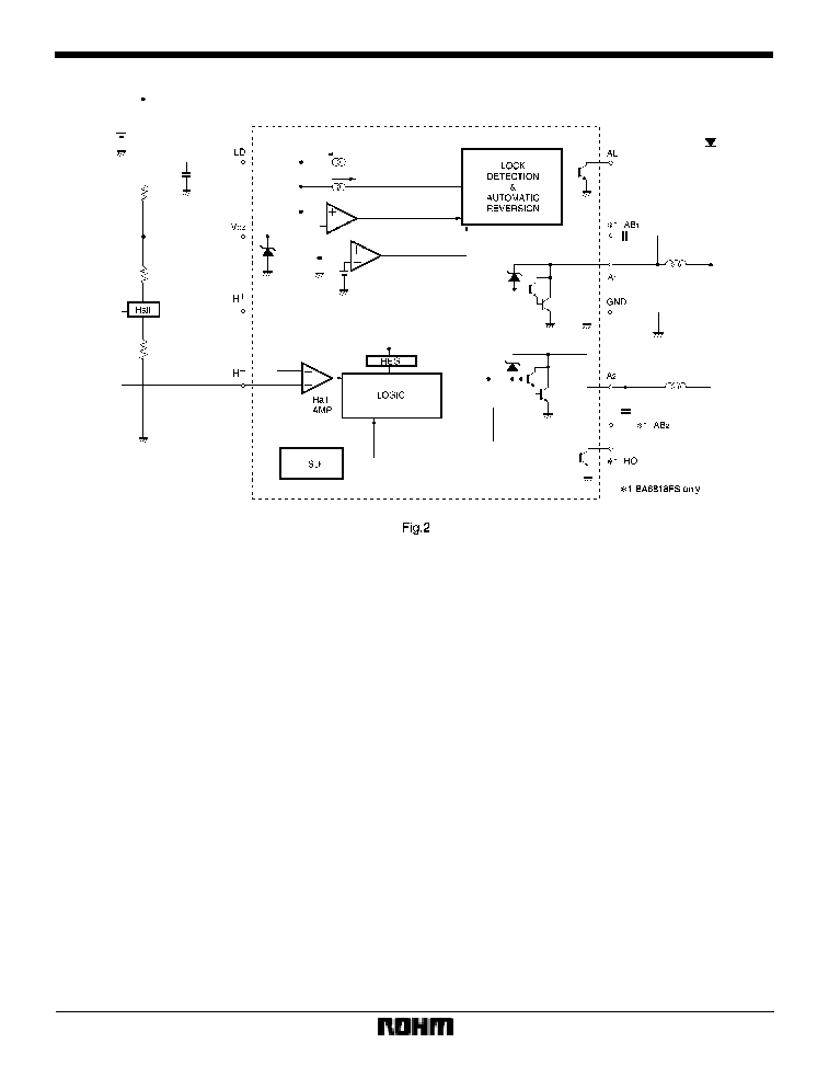
The BA6817F and BA6818FS are 24V motor drivers for 2-phase, half-wave fan motors. The ICs have lock detection
and automatic restart functions. In compact SOP8 (BA6817F) and SSOP-A16 (BA6818FS) packages, the ICs reduce
the number of external components required.
F
Applications
2-phase motors such as fan motors
F
Features
1) Built-in power transistors.
2) Lock detection and automatic restart functions.
3) Thermal shutdown circuit.
4) Alarm output pin. (BA6817F / BA6818FS)
5) Hall signal output pin. (BA6818FS)
F
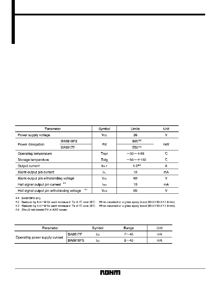
Absolute maximum ratings (Ta = 25
_
C)
F
Recommended operating conditions (Ta = 25
_
C)
719
Motor driver ICs
BA6817F / BA6818FS
F
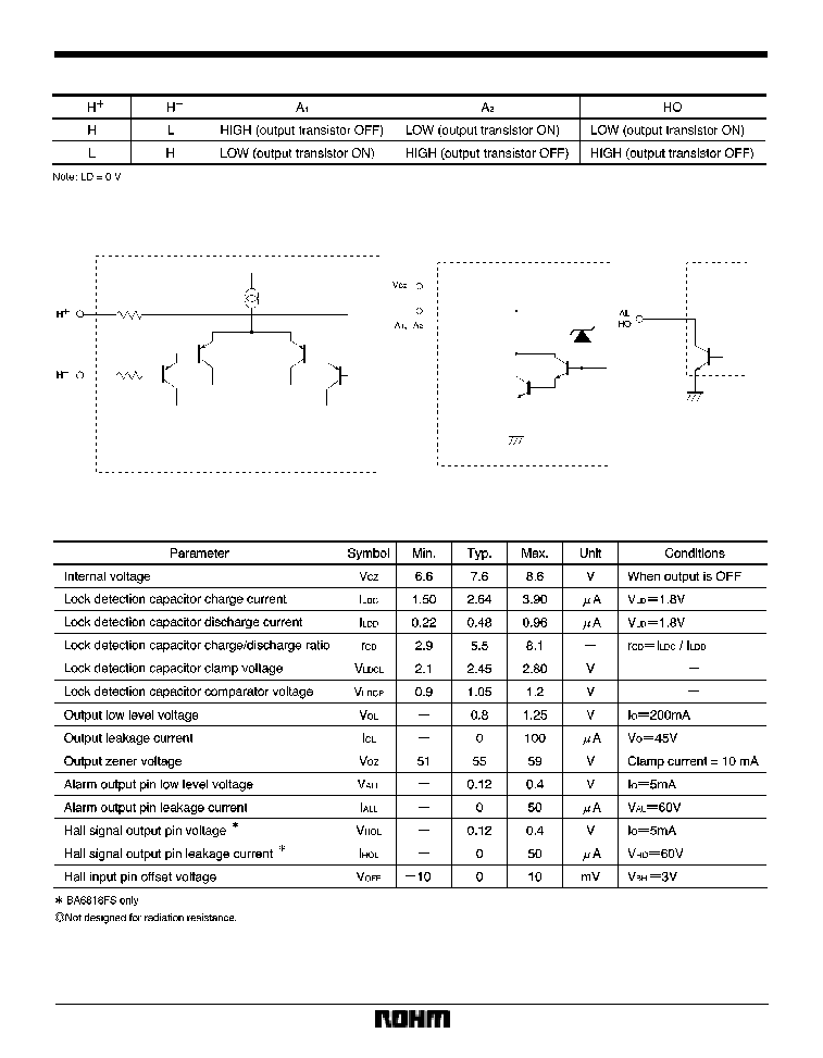
Hall input / output truth table
F
Input / output circuits
F
Electrical characteristics (unless otherwise noted, Ta = 25
_
C)
720
Motor driver ICs
BA6817F / BA6818FS
F
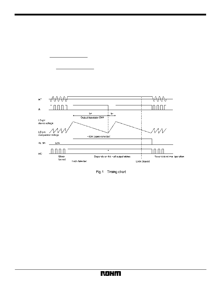
Circuit operation
The BA6817F and BA6818FS have motor lock detection
and automatic restart circuits. The timing of lock detec-
tion and automatic restart is determined by the external
capacitor connected to the LD pin. The charge time of the
external capacitor is given by :
(Typical value)
where
V
LDCL
is the LD-pin clamp voltage
(2.45V),
V
LDCP
is the LD-pin comparator voltage
(1.05V),
I
LDC
is the LD-pin charge current
(2.64
µ
A),
I
LDD
is the LD-pin discharge current
(0.48
µ
A),
C is the capacitance of the LD-pin external capacitor.
For C=0.47
µ
F, for example, the charge (output ON) and
discharge (output OFF) times are 0.24s and 1.37s, re-
spectively.
The timing chart for a motor lock occasion is shown in Fig. 1.
I
LDC
t
on
(Charge time)=
C
S
(V
LDCL
*
V
LDCP
)
I
LDD
t
off
(Discharge time)=
C
S
(V
LDCL
*
V
LDCP
)