640
Audio ICs
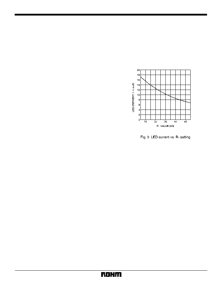
LED level meter driver, 12≠point,
VU scale, dot or bar display
BA682A
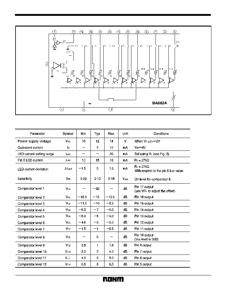
The BA682A is a monolithic IC for LED level meter applications.
The display level range is 13mV
rms
to 327mV
rms
(Typ.), the 0dB level is 130mV
rms
(Typ.) and the VU display is -20dB to
+8dB.
The constant current outputs can be set using external components allowing use of different color LEDs in various com-
binations.
F
Applications
Level meters for all types of audio equipment applications
F
Features
1) 12-point VU display meter driver for bar / dot displays.
2) Fixed-current outputs that can directly drive LEDs.
3) Output current can be set using external resistors al-
lowing different types of LEDs to be used in combina-
tion.
4) Built-in half-wave rectifier amplifier.
5) LED on and off timing can be set using an external
capacitor and resistor.
6) With bar-type display, by connecting four LEDs in se-
ries, power dissipation is reduced.
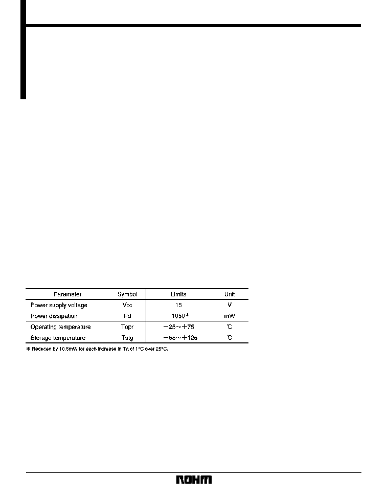
F
Absolute maximum ratings (Ta = 25
_
C)
643
Audio ICs
BA682A
F
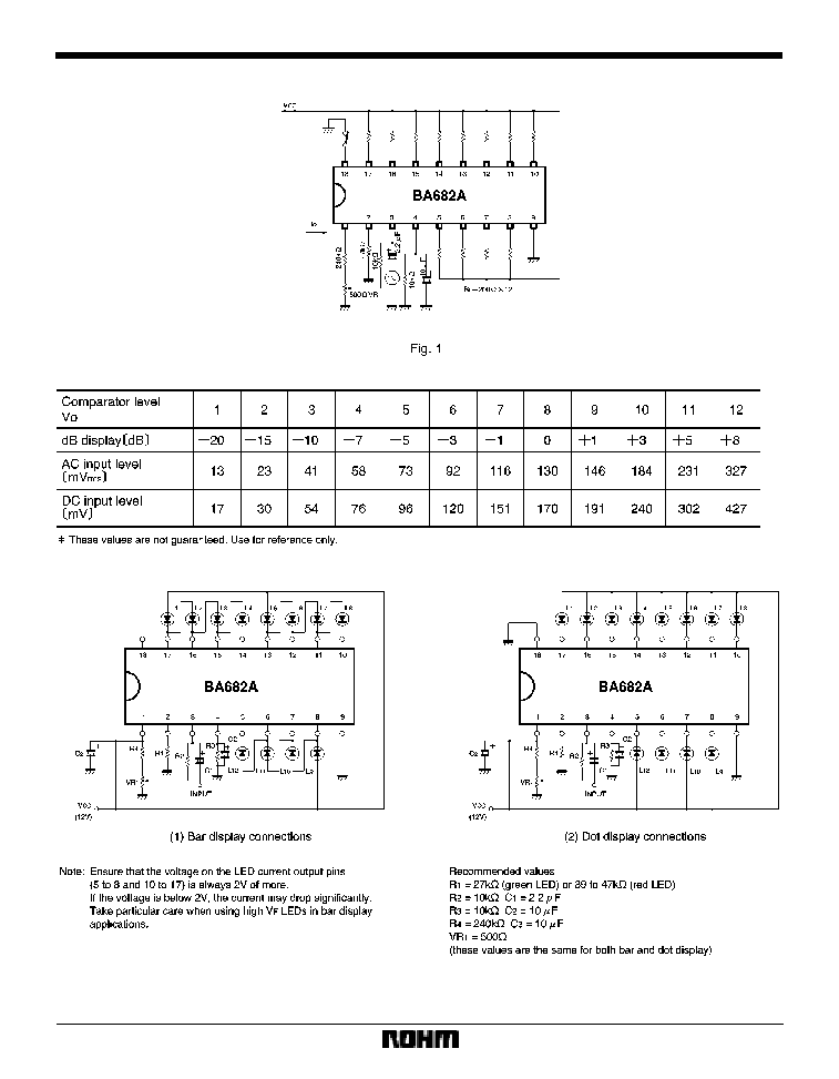
Attached components
(1)
LED current setting resistor (R
1
)
This resistor sets the LED current value. Refer to Fig. 3
for the relationship between the value of this resistor and
the current value. The recommended value is 27k
for
green LEDs, and 39k
for red LEDs. If the LED current
is set too high, the allowable power dissipation of the
package may be exceeded, so exercise due caution.
(2)
Input coupling capacitor (C
1
)
This capacitor connects the BA682A to external input cir-
cuits. The recommended value is 2.2
µ
F.
(3)
Input bias resistor (R
2
)
This resistor is the input impedance. If the value is set too
large, the DC bias voltage will increase, and the input off-
set will increase and have an effect on the comparators.
The recommended value is 10k
.
(4)
Resistor and capacitor that set the LED operation
level discharge time constant (R
3
and C
2
)
These components set the discharge time constant for
LED operation level. The recommended values are R
3
=
10k
and C
2
= 10
µ
F.
(5)
Input offset adjustment resistors (R
4
and VR
1
)
These resistors are used to adjust the input offset for the
rectifier amplifier.
The recommended values are R
4
= 240k
, and VR
1
=
500
. If the value of VR
1
is too high, adjustment becomes
difficult, and if it is too small, adjustment may not be pos-
sible.
(6)
Power supply capacitor (C
3
)
This capacitor stabilizes the power supply line. The rec-
ommended value is 10
µ
F. This capacitor will have no ef-
fect if its value is 1
µ
F or less.
F
Operation notes
(1)
LED connection
Connect the LEDs as indicated in Fig. 2. Note that the
connection methods are different for bar and dot dis-
plays, and that in the case of bar display, pin 18 is open,
while for dot display, pin 18 is connected to GND.
When using different color LEDs that have different cur-
rent values (e.g. green for the lower 10 LEDs and red for
the top two) set the value of the current to the larger LED
current using the external resistor, and adjust the current
value for LEDs that require a smaller current by connect-
ing resistors in parallel them. If you wish to remove LEDs,
do so from the lowest level.
(except when the 12th LED is not used for display align-
ment). Be certain to short unused LEDs.
(2)
LED current adjustment
The LED current is set using R
1
. The relationship be-
tween the value of R
1
and the typical LED current is given
in Fig. 3.
(3)
Comparator voltage
In the case of the BA682A, the comparator voltage is the
input voltage when about half LED current setting value
(typ.) is flowing in an LED.
Therefore, if the LED current is set to 16mA, the
comparator voltage is the value when 8mA is flowing in
the LED.
(4)
0dB and input offset adjustment
First, adjust the input signal so that the 8th LED lights.
This is the 0dB input signal level. Next, lower the input
signal level to -20dB, and adjust the offset adjustment po-
tentiometer VR
1
so that the first LED lights. Repeat the
0dB and -20dB adjustments alternately to accurately set
the levels. The input level at which an LED lights is the
comparator voltage.
(5)
The BA682A GND (pin 9) and the external compo-
nent earths should connected together at one point.