509
Motor driver ICs
Voice coil motor driver
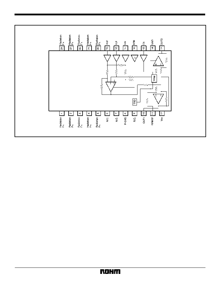
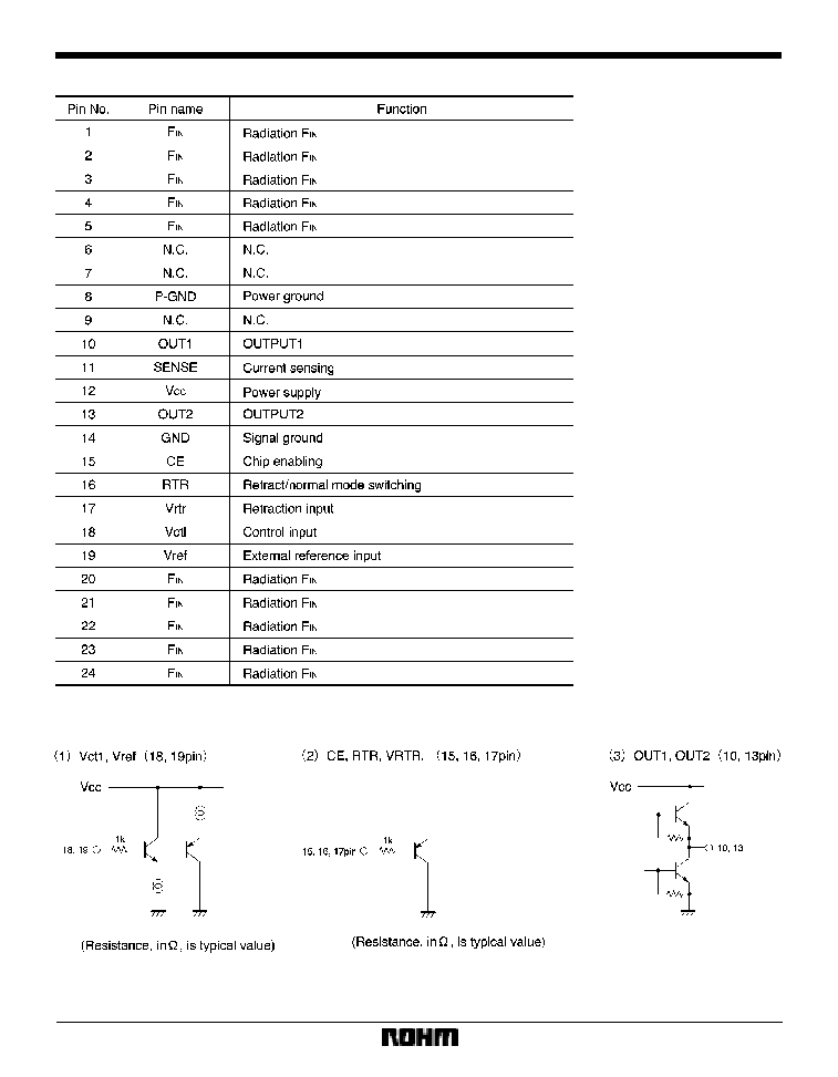
BA6832FS
The BA6832FS is a voice coil motor driver used for moving the heads of hard disc and mass-storage floppy disc drives.
F
Applications
HDD disc and mass-storage FDD
F
Features
1) Output current is controlled by the Vctl-Vref voltage.
2) Retraction control pin.
3) Chip enabling pin.
4) Internal thermal shutdown circuit.
F
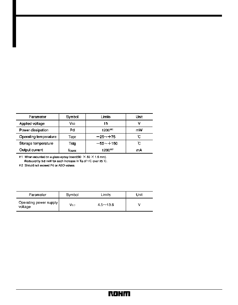
Absolute maximum ratings (Ta = 25
_
C)
F
Recommended operating conditions
513
Motor driver ICs
BA6832FS
F
Circuit operation
(1)
Output current control
The method of output current control depends on wheth-
er the RTL pin is HIGH or LOW.
(
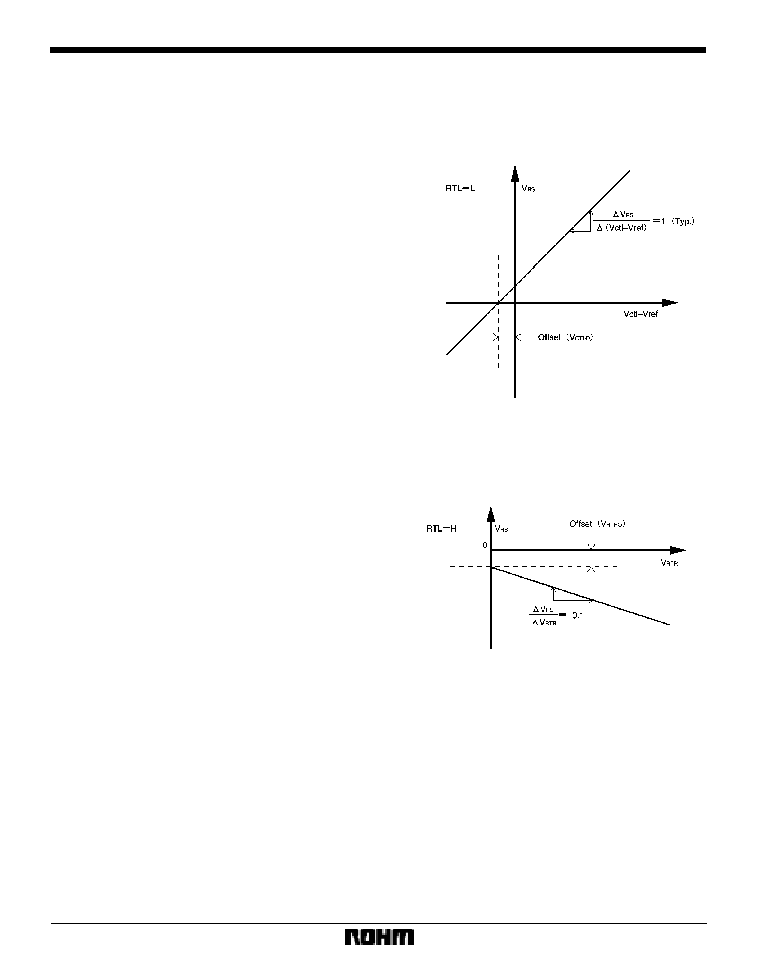
1) When the RTL pin is LOW
The voltage V
RS
that develops across the resistor R
S
be-
tween pins 10 and 11 (with reference to pin 10) is con-
trolled by the voltage between Vctl (pin 18) and Vref (pin
19) :
V
RS
=(Vctl
*
Vref)
1 (Typ.)
The output current I
O
is given by :
I
O
=(Vctl
*
Vref) / Rs (Typ.)
where the positive direction is from pin 13 to pin 10.
Therefore, the voltage-current conversion gain for the
control input is determined by the R
S
value. The gain
band width in this case is 80kHz (typical).
(
2) When the RTL pin is HIGH
The V
RS
voltage (with reference to pin 10) is controlled by
the Vrtr (pin 17) voltage (with reference to the ground) :
V
RS
=
*
0.1
Vrtr / Rs
(
3) RTR threshold
The RTR pin threshold voltage is 1.2
X
1.3V. The pin has
a hysteresis width of about 40mV.
(2)
Standby mode
The standby mode is activated when the CE pin is LOW;
the circuit current is reduced to 0.15mA (typical), and the
output pins are put to the high impedance state. The op-
eration mode is activated when the CE pin is HIGH, and
the output current becomes controllable. The pin's
threshold voltage is 1.2
X
1.3V.
(3)
Internal reference voltage
The internal reference voltage V
reg
is given by :
V
reg
=(V
CC
*
V
F
) / 2
where V
reg
=5.65 when V
CC
=12V. The output pins (pins 10
and 13) operate with reference to V
reg
.