741
Motor driver ICs
Stepping motor driver
BA6846FS / BA6846FV
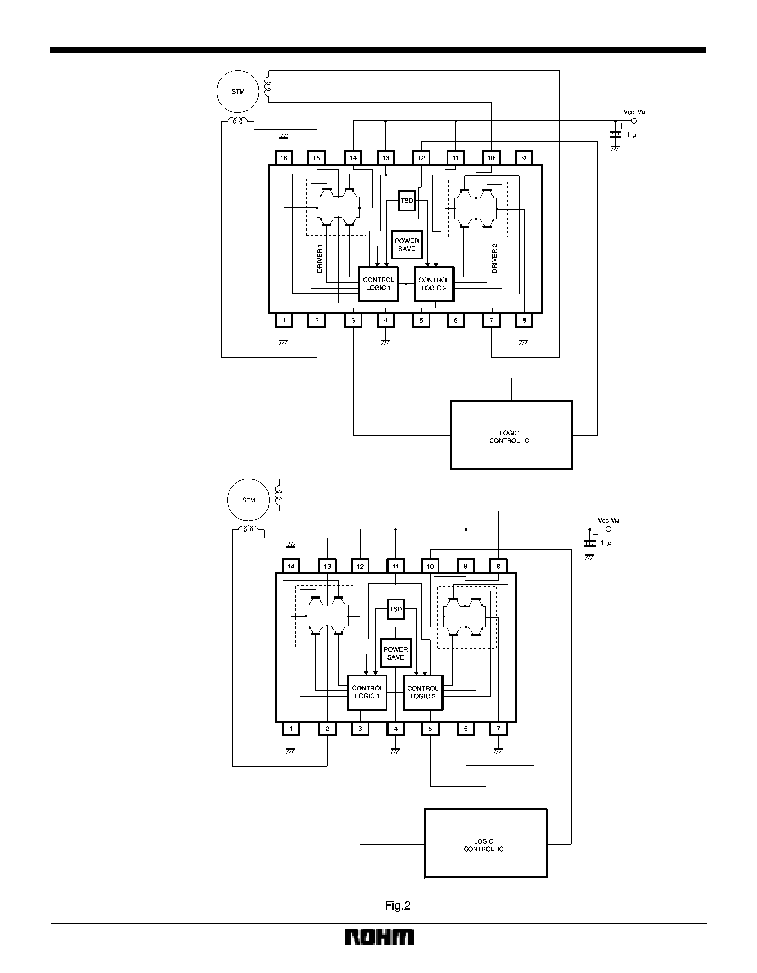
The BA6846FS and BA6846FV are stepping motor drivers with a maximum output current of 0.5A. The logic input allows
three output modes : forward, reverse, and power save. The ICs have low output saturation voltage and are capable
of driving motors at low supply voltage.
F
Applications
Stepping motors for floppy disk drives
F
Features
1) Low output saturation voltage.
2) Power save circuit.
3) Thermal shutdown circuit.
F
Absolute maximum ratings (Ta = 25
_
C)
F
Recommended operating conditions (Ta = 25
_
C)

743
Motor driver ICs
BA6846FS / BA6846FV
F
Input / output circuits
F
Electrical characteristics (unless otherwise noted, Ta = 25
_
C, V
CC
= 5V, V
M
1, 2 = 5V)
F
Input / output truth table
745
Motor driver ICs
BA6846FS / BA6846FV
F
Operation notes
(1)
Control logic pins
Do not apply voltage to control logic pins when the V
CC
voltage is not applied to the IC. The voltage of each pin
should be less than V
CC
, if applied, and should be more
than the ground voltage.
(2)
PCB arrangement
When changing the rotational direction of a motor, a large
current of up to a few hundred milliamperes can flow be-
tween the motor power supply and the PGND pin. De-
pending on the application, this large output current may
flow back to input pins, resulting in output oscillation or
other malfunctions. Make sure that your design does not
allow a common impedance between the large current
output lines and the input section. Suppress the power
supply impedance to low levels, otherwise output oscilla-
tion may occur.
(3)
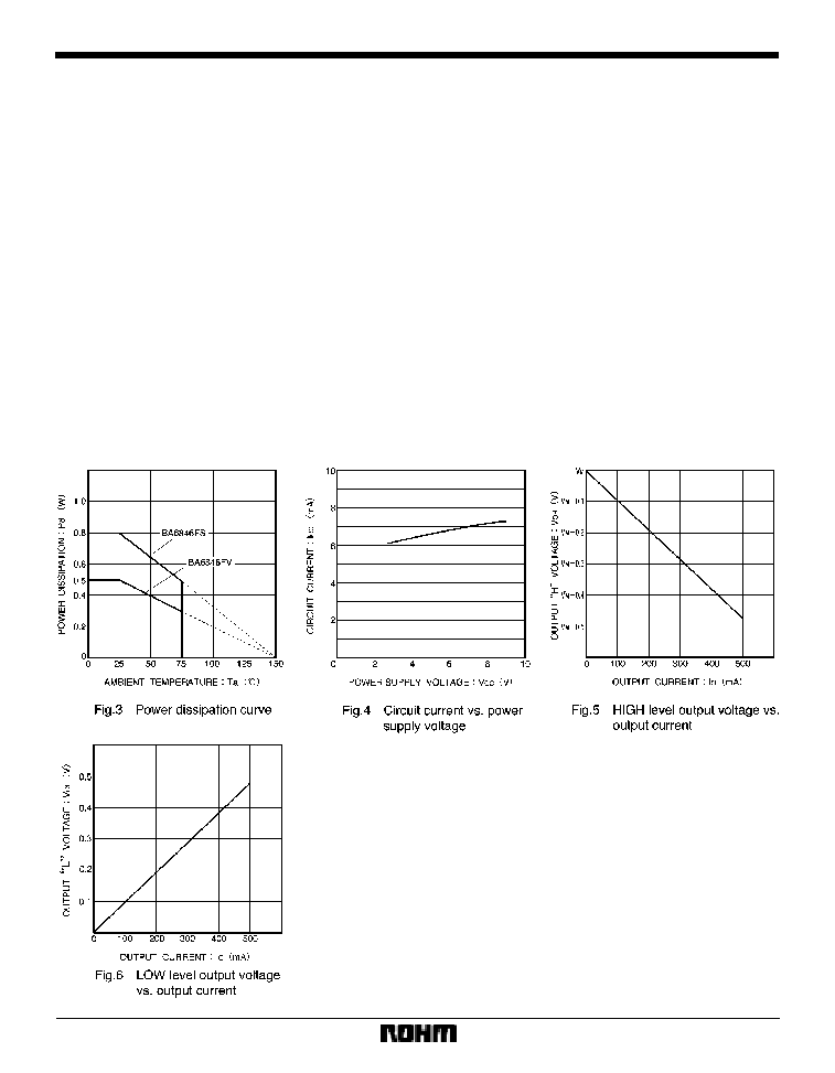
Package power dissipation
The power dissipated by the IC varies widely with the
supply voltage and the output current. Give full consider-
ation to the package power dissipation rating when set-
ting the supply voltage and the output current.
(4)
Ground pins
The GND and SUB pins should have the lowest potential
(ground potential) in the IC.
(5)
Thermal shutdown circuit
This circuit shuts down all the driver outputs when the
chip junction temperature is increased to about 175
_
C
(typical). The thermal shutdown circuit is deactivated
when the temperature drops to about 20
_
C (typical).
(6)
Logic input pins
These pins have characteristics negatively correlated to
temperature. Give full consideration to the temperature
effect when using the IC.
F
Electrical characteristic curves